Racing the Beam
Welcome back to Exploring FPGA Graphics. Last time, we got an introduction to FPGA graphics; let’s put our new graphical skills to work with some simple demo effects. I hope these examples inspire you to create your own effects and improve your hardware design skills.
In this series, we learn about graphics at the hardware level and get a feel for the power of FPGAs. We’ll learn how screens work, play Pong, create starfields and sprites, paint Michelangelo’s David, draw lines and triangles, and animate characters and shapes. New to the series? Start with Beginning FPGA Graphics.
Series Outline
- Beginning FPGA Graphics - video signals and basic graphics
- Racing the Beam (this post) - simple demo effects with minimal logic
- FPGA Pong - recreate the classic arcade on an FPGA
- Display Signals - revisit display signals and meet colour palettes
- Hardware Sprites - fast, colourful graphics for games
- Framebuffers - bitmap graphics featuring Michelangelo’s David
- Lines and Triangles - drawing lines and triangles
- 2D Shapes - filled shapes and simple pictures
- Animated Shapes - animation and double-buffering
Requirements
You should be to run these designs on any recent FPGA board. I include everything you need for the Arty A7-35T, iCEBreaker, Nexys Video, ULX3S, and Verilator Simulation with SDL. See requirements from Beginning FPGA Graphics for more details.
Five Effects
This post features five simple demo effects that generate graphics on the fly:
Find the source and build instructions for all these designs in the projf-explore git repo.
Raster Bars
Raster bars are animated bands of colour created by changing the background colour on every screen line. Raster bars originated on early 8-bit systems, such as Atari 2600, and continue(d) to be popular on home computers, including the Amiga, and Atari ST.
This design creates bars but doesn’t animate them. We’ll look at animation later in this post. You can see animated bars in the rasterbars demo effect.

Design source:
- Arty (XC7): xc7/top_rasterbars.sv
- iCEBreaker (iCE40): ice40/top_rasterbars.sv
- Nexys Video (XC7): xc7-dvi/top_rasterbars.sv
- ULX3S (ECP5): ecp5/top_rasterbars.sv
- Verilator Sim: sim/top_rasterbars.sv
See the README or Sim README for build instructions.
The following Verilog snippet shows the logic that generates the bars:
// screen dimensions (must match display_inst)
localparam V_RES_FULL = 525;  // vertical screen resolution (including blanking)
localparam H_RES      = 640;  // horizontal screen resolution

localparam START_COLR = 12'h126;  // bar start colour (blue: 12'h126) (gold: 12'h640)
localparam COLR_NUM   = 10;       // colours steps in each bar (don't overflow)
localparam LINE_NUM   =  2;       // lines of each colour

logic [11:0] bar_colr;  // 12 bit colour (4 bits per channel)
logic bar_inc;  // increase (or decrease) brightness
logic [$clog2(COLR_NUM):0] cnt_colr;  // count colours in each bar
logic [$clog2(LINE_NUM):0] cnt_line;  // count lines of each colour

// update colour for each screen line
always_ff @(posedge clk_pix) begin
    if (sx == H_RES) begin  // on each screen line at the start of blanking
        if (sy == V_RES_FULL-1) begin  // reset colour on last line of screen
            bar_colr <= START_COLR;
            bar_inc <= 1;  // start by increasing brightness
            cnt_colr <= 0;
            cnt_line <= 0;
        end else if (cnt_line == LINE_NUM-1) begin  // colour complete
            cnt_line <= 0;
            if (cnt_colr == COLR_NUM-1) begin  // switch increase/decrease
                bar_inc <= ~bar_inc;
                cnt_colr <= 0;
            end else begin
                bar_colr <= (bar_inc) ? bar_colr + 12'h111 : bar_colr - 12'h111;
                cnt_colr <= cnt_colr + 1;
            end
        end else cnt_line <= cnt_line + 1;
    end
end

// separate colour channels
logic [3:0] paint_r, paint_g, paint_b;
always_comb {paint_r, paint_g, paint_b} = bar_colr;
As discussed in Beginning FPGA Graphics, we represent colours using a 12-bit RGB hex triplet. For example, #FF0 is orange, #137 is dark blue, and #FFF is white.
Adding 0x111 to a colour increases the brightness of red, green, and blue by one step. To avoid ugly colour jumps, we mustn’t let any colour channel overflow. Our start colour is 12'h126 (dark blue), so we use ten colour steps, finishing with 12'hABF (pale blue). We then reverse direction, subtracting 0x111 from the colour until we return to dark blue.
Try replacing the start colour with 12'h640.
Hitomezashi
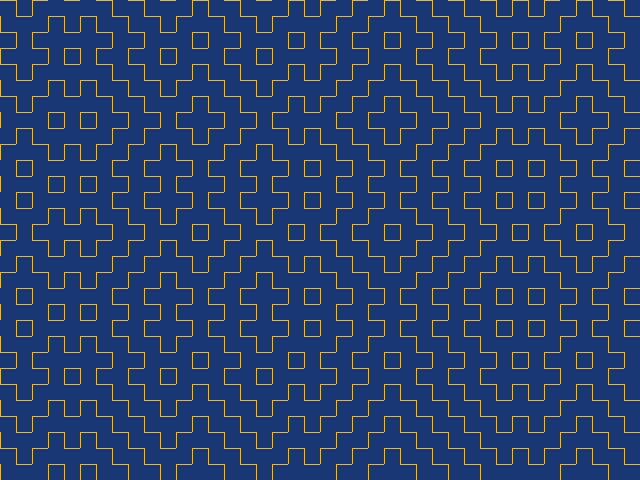
Our second effect was inspired by a Numberphile video: Hitomezashi Stitch Patterns. A short series of 1s and 0s creates a beautiful pattern, which appears both ordered and random. If you’re interested in learning about the origin of these stitch designs, check out Sashiko on Wikipedia.

Design source:
- Arty (XC7): xc7/top_hitomezashi.sv
- iCEBreaker (iCE40): ice40/top_hitomezashi.sv
- Nexys Video (XC7): xc7-dvi/top_hitomezashi.sv
- ULX3S (ECP5): ecp5/top_hitomezashi.sv
- Verilator Sim: sim/top_hitomezashi.sv
See the README or Sim README for build instructions.
This pattern requires only equality and boolean operators:
// stitch start values: MSB first, so we can write left to right
logic [0:39] v_start;  // 40 vertical lines
logic [0:29] h_start;  // 30 horizontal lines

initial begin  // random start values
    v_start = 40'b01100_00101_00110_10011_10101_10101_01111_01101;
    h_start = 30'b10111_01001_00001_10100_00111_01010;
end

// paint stitch pattern with 16x16 pixel grid
logic stitch;
logic v_line, v_on;
logic h_line, h_on;
logic last_h_stitch;
always_comb begin
    v_line = (sx[3:0] == 4'b0000);
    h_line = (sy[3:0] == 4'b0000);
    v_on = sy[4] ^ v_start[sx[9:4]];
    h_on = sx[4] ^ h_start[sy[8:4]];
    stitch = (v_line && v_on) || (h_line && h_on) || last_h_stitch;
end

// last stich fix thanks to Serg Ko (@vfr1200f)
always_ff @(posedge clk_pix) last_h_stitch <= h_line && h_on;

// paint colour: yellow lines, blue background
logic [3:0] paint_r, paint_g, paint_b;
always_comb begin
    paint_r = (stitch) ? 4'hF : 4'h1;
    paint_g = (stitch) ? 4'hC : 4'h3;
    paint_b = (stitch) ? 4'h0 : 4'h7;
end
We draw a line every 16 pixels: 640x480 divided by 16 is 40x30. 40 requires five bits to represent it, while 30 requires only four; otherwise, the horizontal and vertical designs are the same.
The initial block creates a simple ROM to hold our start values. I generated these start values randomly; what happens if you set the start value to all zeros or all ones?
This design makes good use of XOR (exclusive or), denoted by the caret symbol ^.
Hello
A simple ROM can also hold a bitmap pattern.
I’ve chosen the classic greeting, but you can create your own message or picture by altering the initial block. This design uses the compact PICO-8 font, which is in the public domain.

Design source:
- Arty (XC7): xc7/top_hello.sv
- iCEBreaker (iCE40): ice40/top_hello.sv
- Nexys Video (XC7): xc7-dvi/top_hello.sv
- ULX3S (ECP5): ecp5/top_hello.sv
- Verilator Sim: sim/top_hello.sv
See the README or Sim README for build instructions.
This design is little more than an array lookup:
// bitmap: MSB first, so we can write pixels left to right
logic [0:19] bmap [15];  // 20 pixels by 15 lines

initial begin
    bmap[0]  = 20'b1010_1110_1000_1000_0110;
    bmap[1]  = 20'b1010_1000_1000_1000_1010;
    bmap[2]  = 20'b1110_1100_1000_1000_1010;
    bmap[3]  = 20'b1010_1000_1000_1000_1010;
    bmap[4]  = 20'b1010_1110_1110_1110_1100;
    bmap[5]  = 20'b0000_0000_0000_0000_0000;
    bmap[6]  = 20'b1010_0110_1110_1000_1100;
    bmap[7]  = 20'b1010_1010_1010_1000_1010;
    bmap[8]  = 20'b1010_1010_1100_1000_1010;
    bmap[9]  = 20'b1110_1010_1010_1000_1010;
    bmap[10] = 20'b1110_1100_1010_1110_1110;
    bmap[11] = 20'b0000_0000_0000_0000_0000;
    bmap[12] = 20'b0000_0000_0000_0000_0000;
    bmap[13] = 20'b0000_0000_0000_0000_0000;
    bmap[14] = 20'b0000_0000_0000_0000_0000;
end

// paint at 32x scale in active screen area
logic picture;
logic [4:0] x;  // 20 columns need five bits
logic [3:0] y;  // 15 rows need four bits
always_comb begin
    x = sx[9:5];  // every 32 horizontal pixels
    y = sy[8:5];  // every 32 vertical pixels
    picture = de ? bmap[y][x] : 0;  // look up pixel (unless we're in blanking)
end

// paint colour: yellow lines, blue background
logic [3:0] paint_r, paint_g, paint_b;
always_comb begin
    paint_r = (picture) ? 4'hF : 4'h1;
    paint_g = (picture) ? 4'hC : 4'h3;
    paint_b = (picture) ? 4'h0 : 4'h7;
end
Typically, vectors are defined [19:0] (LSB first) rather than [0:19] (MSB first). We use MSB first to write the pixels left to right as they appear on the screen. You can learn more on this topic from Verilog Vectors and Arrays.
We cover bitmap graphics in detail later in this series when we discuss Framebuffers.
Colour Cycle
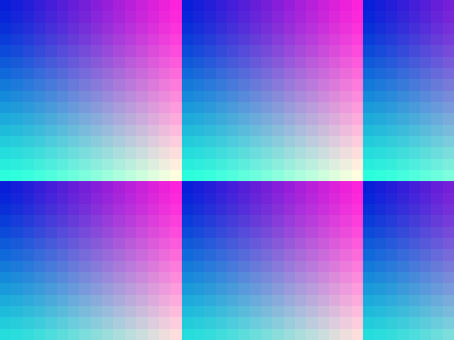
So far, we’ve created static designs. This effect takes the colour gradient from Beginning FPGA Graphics and cycles through all 16 blue levels. This design lets you see all 4096 colours our 12-bit graphics output supports.

Design source:
- Arty (XC7): xc7/top_colour_cycle.sv
- iCEBreaker (iCE40): ice40/top_colour_cycle.sv
- Nexys Video (XC7): xc7-dvi/top_colour_cycle.sv
- ULX3S (ECP5): ecp5/top_colour_cycle.sv
- Verilator Sim: sim/top_colour_cycle.sv
See the README or Sim README for build instructions.
This design is built around a frame counter:
// screen dimensions (must match display_inst)
localparam V_RES = 480;  // vertical screen resolution

logic frame;  // high for one clock tick at the start of vertical blanking
always_comb frame = (sy == V_RES && sx == 0);

// update the colour level every N frames
localparam FRAME_NUM = 30;  // frames between colour level change
logic [$clog2(FRAME_NUM):0] cnt_frame;  // frame counter
logic [3:0] colr_level;  // level of colour being cycled

always_ff @(posedge clk_pix) begin
    if (frame) begin
        if (cnt_frame == FRAME_NUM-1) begin  // every FRAME_NUM frames
            cnt_frame <= 0;
            colr_level <= colr_level + 1;
        end else cnt_frame <= cnt_frame + 1;
    end
end

// paint colour: based on screen position
logic [3:0] paint_r, paint_g, paint_b;
always_comb begin
    paint_r = sx[7:4];  // 16 horizontal pixels of each red level
    paint_g = sy[7:4];  // 16 vertical pixels of each green level
    paint_b = colr_level;  // blue level changes over time
end
Once per frame, at the start of vertical blanking, we update a counter, cnt_frame. We determine the counter width using $clog2, so it’s always the correct size.
I’ve chosen to update the colour every 30 frames (0.5 seconds). Change the value of FRAME_NUM to set the cycle speed.
When the blue intensity reaches 0xF, it automatically overflows to 0x0, creating a disconcerting jump in the blue level. Try updating the design so the blue level smoothly falls and rises; you can use the raster bars design for inspiration.
Bounce
This effect bounces the ‘blue Peter’ square around the screen:

Design source:
- Arty (XC7): xc7/top_bounce.sv
- iCEBreaker (iCE40): ice40/top_bounce.sv
- Nexys Video (XC7): xc7-dvi/top_bounce.sv
- ULX3S (ECP5): ecp5/top_bounce.sv
- Verilator Sim: sim/top_bounce.sv
See the README or Sim README for build instructions.
On the surface, bouncing seems simple: reverse direction when we hit an edge. In practice, it’s more complex: we need to account for the square’s size and speed.
I’ve chosen to draw the square at the edge of the screen when it collides, irrespective of its speed and position.
// screen dimensions (must match display_inst)
localparam H_RES = 640;  // horizontal screen resolution
localparam V_RES = 480;  // vertical screen resolution

logic frame;  // high for one clock tick at the start of vertical blanking
always_comb frame = (sy == V_RES && sx == 0);

// frame counter lets us to slow down the action
localparam FRAME_NUM = 1;  // slow-mo: animate every N frames
logic [$clog2(FRAME_NUM):0] cnt_frame;  // frame counter
always_ff @(posedge clk_pix) begin
    if (frame) cnt_frame <= (cnt_frame == FRAME_NUM-1) ? 0 : cnt_frame + 1;
end

// square parameters
localparam Q_SIZE = 200;   // size in pixels
logic [CORDW-1:0] qx, qy;  // position (origin at top left)
logic qdx, qdy;            // direction: 0 is right/down
logic [CORDW-1:0] qs = 2;  // speed in pixels/frame

// update square position once per frame
always_ff @(posedge clk_pix) begin
    if (frame && cnt_frame == 0) begin
        // horizontal position
        if (qdx == 0) begin  // moving right
            if (qx + Q_SIZE + qs >= H_RES-1) begin  // hitting right of screen?
                qx <= H_RES - Q_SIZE - 1;  // move right as far as we can
                qdx <= 1;  // move left next frame
            end else qx <= qx + qs;  // continue moving right
        end else begin  // moving left
            if (qx < qs) begin  // hitting left of screen?
                qx <= 0;  // move left as far as we can
                qdx <= 0;  // move right next frame
            end else qx <= qx - qs;  // continue moving left
        end

        // vertical position
        if (qdy == 0) begin  // moving down
            if (qy + Q_SIZE + qs >= V_RES-1) begin  // hitting bottom of screen?
                qy <= V_RES - Q_SIZE - 1;  // move down as far as we can
                qdy <= 1;  // move up next frame
            end else qy <= qy + qs;  // continue moving down
        end else begin  // moving up
            if (qy < qs) begin  // hitting top of screen?
                qy <= 0;  // move up as far as we can
                qdy <= 0;  // move down next frame
            end else qy <= qy - qs;  // continue moving up
        end
    end
end

// define a square with screen coordinates
logic square;
always_comb begin
    square = (sx >= qx) && (sx < qx + Q_SIZE) && (sy >= qy) && (sy < qy + Q_SIZE);
end

// paint colour: white inside square, blue outside
logic [3:0] paint_r, paint_g, paint_b;
always_comb begin
    paint_r = (square) ? 4'hF : 4'h1;
    paint_g = (square) ? 4'hF : 4'h3;
    paint_b = (square) ? 4'hF : 4'h7;
end
ProTip: Our coordinates are unsigned, so (qx < 0) is always true.
Explore
I hope you enjoyed this instalment of Exploring FPGA Graphics, but nothing beats creating your own designs. Here are a few suggestions to get you started:
- Display your own message in place of ‘Hello World’
- Animate raster bars - see rasterbars demo effect for one interpretation
- Change the colour of the square each time it bounces
- Combine multiple effects into a single demo
What’s Next?
Next time on FPGA Graphics, we’ll be playing Pong against our FPGA.
I’m currently adding ULX3S (ECP5) support to the FPGA Graphics series and expect to complete this work before the end of 2025.
Acknowledgements
Thanks to Serg Ko for the hitomezashi missing pixel fix.