Beginning FPGA Graphics
Welcome to Exploring FPGA Graphics. In this series, we learn about graphics at the hardware level and get a feel for the power of FPGAs. We’ll learn how screens work, play Pong, create starfields and sprites, paint Michelangelo’s David, draw lines and triangles, and animate characters and shapes. Along the way, you’ll experience a range of designs and techniques, from memory and finite state machines to crossing clock domains and translating C algorithms into Verilog.
In this first part, we’ll learn how screens work and create simple graphics in logic.
Series Outline
- Beginning FPGA Graphics (this post) - video signals and basic graphics
- Racing the Beam - simple demo effects with minimal logic
- FPGA Pong - recreate the classic arcade on an FPGA
- Display Signals - revisit display signals and meet colour palettes
- Hardware Sprites - fast, colourful graphics for games
- Framebuffers - bitmap graphics featuring Michelangelo’s David
- Lines and Triangles - drawing lines and triangles
- 2D Shapes - filled shapes and simple pictures
- Animated Shapes - animation and double-buffering
Requirements
For this series, you need an FPGA board with video output. We’ll work at 640x480, so almost any video output will work. It helps to be comfortable programming your FPGA board and reasonably familiar with Verilog. If you don’t have a dev board, don’t worry; you can use the Verilator simulator.
We’ll demonstrate the designs with four boards and one simulator:
- Arty A7-35T (Xilinx Artix-7) with Pmod VGA
- iCEBreaker (Lattice iCE40) with 12-Bit DVI Pmod
- Nexys Video (Xilinx Artix-7) with on-board HDMI connector
- ULX3S (Lattice ECP5) with on-board HDMI connector
- Verilator Simulation with SDL - free hardware sim that runs on your PC (Linux/Mac/Windows)
Nexys Video and ULX3S DVI Output
We’ll generate a 1280x720p60 DVI signal on the Nexys Video and ULX3S, but the principles and graphics designs are very similar. The DVI signal is HDMI compatible, so you can connect your board to an HDMI monitor or television. I use the DVI output for video capture at Project F. A forthcoming post will cover TMDS signal generation.

Source
The SystemVerilog designs featured in this series are available from the projf-explore git repo under the open-source MIT licence: build on them to your heart’s content. The rest of the blog content is subject to standard copyright restrictions: don’t republish it without permission.
SystemVerilog
We’ll use a few features from SystemVerilog to make Verilog a little more pleasant. If you’re familiar with Verilog, you’ll be fine. All the SystemVerilog features used are compatible with recent versions of Verilator, Yosys, Icarus Verilog, and Xilinx Vivado.
Space and Time
A screen is a miniature universe with its own space and time.
Seen from afar, a screen shows a smooth two-dimensional image. Up close, it breaks up into many individual blocks of colour: red, green, and blue. We hide this complexity behind the abstract idea of a pixel: the smallest part of the screen we can control. A typical HD screen is 1920 by 1080: two million pixels in total. Even a 640x480 display has more than 300,000 pixels.
A screen creates the illusion of movement by refreshing many times every second. At 60 Hz, a 1920x1080 screen draws 124 million pixels every second! The need to quickly handle so much data is a big part of the challenge of working with graphics at a hardware level.
Display connectors and cabling vary, but VGA, HDMI, and DisplayPort have similar data designs. There are three channels for colour, usually red, green, and blue, and horizontal and vertical sync signals. There may also be audio and configuration data, but that’s not important right now.
The red, green, and blue channels carry the colour of each pixel in turn. A screen begins a new line when it receives a horizontal sync and a new frame on a vertical sync. The sync signals are part of blanking intervals.
Blanking intervals allow time for the electron gun in cathode ray tubes (CRTs) to move to the following line (horizontal retrace) or the top of the screen (vertical retrace). Modern digital displays have retained the blanking intervals and repurposed them to transmit audio and other data.
Check out Tim Hunkin’s Secret Life of the Television (1987) to see a CRT television cut in half and its inner workings revealed.

Display Timings
A screen mode is defined by its display timings. Standard timings are set by VESA and the CTA.
In this series, we’ll use 640x480 at 60Hz. Almost all displays support 640x480, and its low resource requirements make it feasible to work with even the smallest FPGAs.
Display timings for 640x480 at 60Hz in units of pixels:
| Parameter | Horizontal | Vertical |
|---|---|---|
| Active Pixels | 640 | 480 |
| Front Porch | 16 | 10 |
| Sync Width | 96 | 2 |
| Back Porch | 48 | 33 |
| Total Blanking | 160 | 45 |
| Total Pixels | 800 | 525 |
| Sync Polarity | negative | negative |
For other screen modes (including 1280x720p60) see Video Timings: VGA, SVGA, 720p, 1080p.
The blanking interval has three parts: front porch, sync, and back porch. The front porch occurs before the sync signal and the back porch after.
If your screen showed all parts of the signal, it would look something like this:

Including blanking, we have a total of 800x525 pixels.
The refresh rate is 60 Hz, so the total number of pixels per second is:
800 x 525 x 60 = 25,200,000
Therefore, we need a pixel clock of 25.2 MHz.
ProTip: The pixel clock is also known as the dot clock.
Driving a Display
Having selected our display timings, we’re ready to create a video signal. There are four stages:
- Pixel Clock
- Display Signals
- Drawing Graphics
- Video Output (VGA, HDMI, DisplayPort)

Pixel Clock
We know we need a frequency of 25.2 MHz, but how to reach it?
FPGAs include phase-locked loops (PLLs) to generate custom clock frequencies. Alas, there isn’t a standard way to configure a PLL; we need a vendor-specific design.
I have provided implementations for our boards:
- Arty (XC7): xc7/clock_480p.sv
- iCEBreaker (iCE40): ice40/clock_480p.sv
- Nexys Video (XC7): xc7-dvi/clock_720p.sv (74.25 MHz for 720p60)
- ULX3S (ECP5): ecp5/clock2_gen.v (74 MHz for 720p60)
NB. The iCEBreaker can’t generate 25.2 MHz but runs fine at 25.125 MHz.
For other FPGA architectures, you’ll need to consult your vendor documentation. If you can’t reach 25.2 MHz exactly, 25 MHz or thereabouts should be fine.
CAUTION: CRT Monitors
Modern displays, including multisync CRTs, should be fine with a 25.2 or 25 MHz pixel clock. An out-of-spec signal could damage fixed-frequency CRTs, such as the original IBM 85xx series. Use these designs at your own risk.
Display Signals
Next, we can generate sync signals from our pixel clock and display timings. We also want to report the current screen position to know when to draw things.
We do both of these things with a simple display module [simple_480p.sv]:
module simple_480p (
    input  wire logic clk_pix,   // pixel clock
    input  wire logic rst_pix,   // reset in pixel clock domain
    output      logic [9:0] sx,  // horizontal screen position
    output      logic [9:0] sy,  // vertical screen position
    output      logic hsync,     // horizontal sync
    output      logic vsync,     // vertical sync
    output      logic de         // data enable (low in blanking interval)
    );

    // horizontal timings
    parameter HA_END = 639;           // end of active pixels
    parameter HS_STA = HA_END + 16;   // sync starts after front porch
    parameter HS_END = HS_STA + 96;   // sync ends
    parameter LINE   = 799;           // last pixel on line (after back porch)

    // vertical timings
    parameter VA_END = 479;           // end of active pixels
    parameter VS_STA = VA_END + 10;   // sync starts after front porch
    parameter VS_END = VS_STA + 2;    // sync ends
    parameter SCREEN = 524;           // last line on screen (after back porch)

    always_comb begin
        hsync = ~(sx >= HS_STA && sx < HS_END);  // invert: negative polarity
        vsync = ~(sy >= VS_STA && sy < VS_END);  // invert: negative polarity
        de = (sx <= HA_END && sy <= VA_END);
    end

    // calculate horizontal and vertical screen position
    always_ff @(posedge clk_pix) begin
        if (sx == LINE) begin  // last pixel on line?
            sx <= 0;
            sy <= (sy == SCREEN) ? 0 : sy + 1;  // last line on screen?
        end else begin
            sx <= sx + 1;
        end
        if (rst_pix) begin
            sx <= 0;
            sy <= 0;
        end
    end
endmodule
ProTip: The last assignment wins in Verilog, so the reset overrides existing values for sx and sy.
sx and sy store the horizontal and vertical screen positions. Counting starts at zero, so the maximum values are 799 for sx and 524 for sy, requiring 10 bits to hold the coordinates (210 = 1024).
For simplicity, we put blanking after the visible pixels; that way, (0,0) is the top-left visible pixel and (639,479) is the bottom right.
The following diagram shows the display signals to scale with two 64x64 pixel squares drawn:
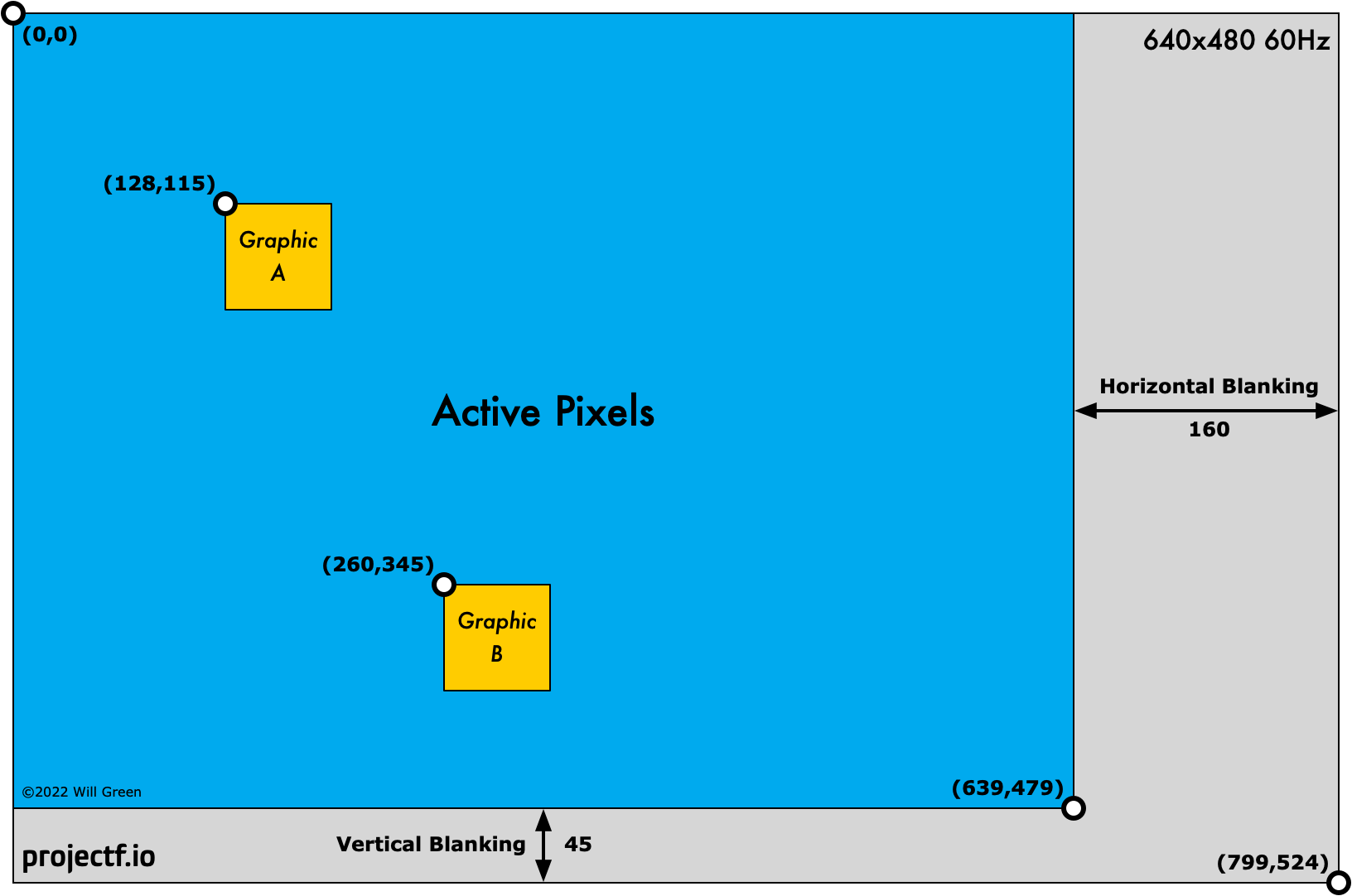
de is data enable, which is low during the blanking interval (the grey area in the above diagram) and tells us when it’s safe to draw.
From the display timings, we know our sync polarity is negative for both hsync and vsync. Negative polarity means that a low voltage indicates a sync.
The following simulation shows the vertical sync starting at line 489. The vertical sync is low for two lines, as expected from the display timings. Note the horizontal sync at the end of each line.

Test Benches
If you’re using Vivado, try exercising the designs with these test benches:
Some things to check:
- What is the pixel clock period?
- How long does the pixel clock take to lock?
- Does a frame last precisely 1/60th of a second?
- How much time does a single line last?
- What are the maximum values of
sxandsywhendeis low?
You can find instructions for running the Vivado simulations in the source README.
Drawing Graphics
For our first design, we’re going to draw a square like this:

We use the screen coordinates (sx,sy) to define a square in the centre of the screen:
logic square;
always_comb begin
    square = (sx > 220 && sx < 420) && (sy > 140 && sy < 340);
end
12-bit Colour
The VGA and DVI Pmods output 12-bit colour with three 4-bit channels: red, green, and blue.
We can represent a specific colour using a hex triplet:
#F00- bright red#FA0- orange#0E3- bright green#137- dark blue#FFF- white
In Verilog, hex literals use the letter h, so we can set our colours as follows:
// paint colour: white inside square, blue outside
logic [3:0] paint_r, paint_g, paint_b;
always_comb begin
    paint_r = (square) ? 4'hF : 4'h1;
    paint_g = (square) ? 4'hF : 4'h3;
    paint_b = (square) ? 4'hF : 4'h7;
end
We generate a separate paint signal for each colour channel, but before we send it to the screen, we need to consider blanking. During the blanking interval, it’s vital that the colour levels are zero (black); otherwise, you may see artefacts or distortion.
In the blanking interval, de is low, and we set the output to zero for all three channels:
// display colour: paint colour but black in blanking interval
logic [3:0] display_r, display_g, display_b;
always_comb begin
    display_r = (de) ? paint_r : 4'h0;
    display_g = (de) ? paint_g : 4'h0;
    display_b = (de) ? paint_b : 4'h0;
end
Video Output
Video output works differently for each board and simulation, so we’ll cover them in turn.
Arty VGA
VGA output is straightforward. We register each signal to improve timing and avoid skew:
// VGA Pmod output
always_ff @(posedge clk_pix) begin
    vga_hsync <= hsync;
    vga_vsync <= vsync;
    vga_r <= display_r;
    vga_g <= display_g;
    vga_b <= display_b;
end
The VGA Pmod handles the conversion of digital colour signals into analogue voltages.
iCEBreaker DVI
The TFP410 chip on the DVI Pmod takes our colour and sync signals and encodes them into DVI using Transition-minimized differential signalling (TMDS).
We use the SB_IO primitive to produce high-quality output from the iCE40 FPGA. It’s not necessary to understand how SB_IO works for this series; use this snippet in your designs, and all will be well:
// DVI Pmod output
SB_IO #(
    .PIN_TYPE(6'b010100)  // PIN_OUTPUT_REGISTERED
) dvi_signal_io [14:0] (
    .PACKAGE_PIN({dvi_hsync, dvi_vsync, dvi_de, dvi_r, dvi_g, dvi_b}),
    .OUTPUT_CLK(clk_pix),
    .D_OUT_0({hsync, vsync, de, display_r, display_g, display_b}),
    .D_OUT_1()
);

// DVI Pmod clock output: 180° out of phase with other DVI signals
SB_IO #(
    .PIN_TYPE(6'b010000)  // PIN_OUTPUT_DDR
) dvi_clk_io (
    .PACKAGE_PIN(dvi_clk),
    .OUTPUT_CLK(clk_pix),
    .D_OUT_0(1'b0),
    .D_OUT_1(1'b1)
);
Lattice SB_IO
The SB_IO primitive (with registered outputs) ensures our DVI signals are in sync when they leave the FPGA. The DVI clock is 180 degrees out of phase, so the TFP410 will sample the middle of the colour values. You can learn more about iCE primitives from the Lattice ICE Technology Library.
Nexys Video and ULX3S
The Nexys Video and ULX3S DVI output is more complex than the other boards and I won’t go into details here. I plan to cover DVI/HDMI signals in a future blog post.
Verilator Sim
The simulation output is similar to the Arty VGA, but it expects eight bits per colour channel:
// SDL output (8 bits per colour channel)
always_ff @(posedge clk_pix) begin
    sdl_sx <= sx;
    sdl_sy <= sy;
    sdl_de <= de;
    sdl_r <= {2{display_r}};  // double signal width from 4 to 8 bits
    sdl_g <= {2{display_g}};
    sdl_b <= {2{display_b}};
end
Square One
Bringing the four stages together, we have a complete top module:
- Arty (XC7): xc7/top_square.sv
- iCEBreaker (iCE40): ice40/top_square.sv
- Nexys Video (XC7): xc7-dvi/top_square.sv
- ULX3S (ECP5): ecp5/top_square.sv
- Verilator Sim: sim/top_square.sv
See if you can match the four stages of driving a display with the Verilog for your board.
In addition to the source links (above) I have included the source listing for Arty and Verilator below.
Arty VGA Square
module top_square (
    input  wire logic clk_100m,     // 100 MHz clock
    input  wire logic btn_rst_n,    // reset button
    output      logic vga_hsync,    // VGA horizontal sync
    output      logic vga_vsync,    // VGA vertical sync
    output      logic [3:0] vga_r,  // 4-bit VGA red
    output      logic [3:0] vga_g,  // 4-bit VGA green
    output      logic [3:0] vga_b   // 4-bit VGA blue
    );

    // generate pixel clock
    logic clk_pix;
    logic clk_pix_locked;
    clock_480p clock_pix_inst (
       .clk_100m,
       .rst(!btn_rst_n),  // reset button is active low
       .clk_pix,
       .clk_pix_5x(),  // not used for VGA output
       .clk_pix_locked
    );

    // display sync signals and coordinates
    localparam CORDW = 10;  // screen coordinate width in bits
    logic [CORDW-1:0] sx, sy;
    logic hsync, vsync, de;
    simple_480p display_inst (
        .clk_pix,
        .rst_pix(!clk_pix_locked),  // wait for clock lock
        .sx,
        .sy,
        .hsync,
        .vsync,
        .de
    );

    // define a square with screen coordinates
    logic square;
    always_comb begin
        square = (sx > 220 && sx < 420) && (sy > 140 && sy < 340);
    end

    // paint colour: white inside square, blue outside
    logic [3:0] paint_r, paint_g, paint_b;
    always_comb begin
        paint_r = (square) ? 4'hF : 4'h1;
        paint_g = (square) ? 4'hF : 4'h3;
        paint_b = (square) ? 4'hF : 4'h7;
    end

    // display colour: paint colour but black in blanking interval
    logic [3:0] display_r, display_g, display_b;
    always_comb begin
        display_r = (de) ? paint_r : 4'h0;
        display_g = (de) ? paint_g : 4'h0;
        display_b = (de) ? paint_b : 4'h0;
    end

    // VGA Pmod output
    always_ff @(posedge clk_pix) begin
        vga_hsync <= hsync;
        vga_vsync <= vsync;
        vga_r <= display_r;
        vga_g <= display_g;
        vga_b <= display_b;
    end
endmodule
Verilator Sim
The Verilator simulation works a little differently; we output the coordinates sdl_sx, sdl_sy, and the colour information.
module top_square #(parameter CORDW=10) (  // coordinate width
    input  wire logic clk_pix,             // pixel clock
    input  wire logic sim_rst,             // sim reset
    output      logic [CORDW-1:0] sdl_sx,  // horizontal SDL position
    output      logic [CORDW-1:0] sdl_sy,  // vertical SDL position
    output      logic sdl_de,              // data enable (low in blanking interval)
    output      logic [7:0] sdl_r,         // 8-bit red
    output      logic [7:0] sdl_g,         // 8-bit green
    output      logic [7:0] sdl_b          // 8-bit blue
    );

    // display sync signals and coordinates
    logic [CORDW-1:0] sx, sy;
    logic de;
    simple_480p display_inst (
        .clk_pix,
        .rst_pix(sim_rst),
        .sx,
        .sy,
        .hsync(),
        .vsync(),
        .de
    );

    // define a square with screen coordinates
    logic square;
    always_comb begin
        square = (sx > 220 && sx < 420) && (sy > 140 && sy < 340);
    end

    // paint colour: white inside square, blue outside
    logic [3:0] paint_r, paint_g, paint_b;
    always_comb begin
        paint_r = (square) ? 4'hF : 4'h1;
        paint_g = (square) ? 4'hF : 4'h3;
        paint_b = (square) ? 4'hF : 4'h7;
    end

    // display colour: paint colour but black in blanking interval
    logic [3:0] display_r, display_g, display_b;
    always_comb begin
        display_r = (de) ? paint_r : 4'h0;
        display_g = (de) ? paint_g : 4'h0;
        display_b = (de) ? paint_b : 4'h0;
    end

    // SDL output (8 bits per colour channel)
    always_ff @(posedge clk_pix) begin
        sdl_sx <= sx;
        sdl_sy <= sy;
        sdl_de <= de;
        sdl_r <= {2{display_r}};  // double signal width from 4 to 8 bits
        sdl_g <= {2{display_g}};
        sdl_b <= {2{display_b}};
    end
endmodule
NB. The Verilator simulation receives its pixel clock from the C++ wrapper.
Constraints
Before building the design, we need board constraints. The constraints map the pins on the FPGA to the signals in our design. For example, we need to know which FPGA pin connects to the reset button and which to the vertical sync.
Take a look at the constraints for your board:
- Arty Constraints: arty.xdc
- iCEBreaker Constraints: icebreaker.pcf
- Nexys Video Constraints: nexys_video.xdc
- ULX3S Constraints: ulx3s.lpf
The Verilator sim doesn’t require constraints.
Building
Each part of this series includes a README and Verilator Sim README with build instructions.
This section provides a basic build guide to get you started. If you need help with your board, I recommend the Digilent Forum for Digilent boards, 1BitSquared Discord for iCEBreaker, and the Radiona Discord for ULX3S.
Arty
We build Arty designs using Xilinx Vivado. To create a Vivado project, clone the projf-explore repo from GitHub. Then, start Vivado and run the following in the Tcl Console:
cd projf-explore/graphics/fpga-graphics/xc7/vivado
source ./create_project.tcl
This creates a Vivado project with all four Arty designs. The path is xc7 for Arty.
iCEBreaker
We build iCEBreaker designs with the open-source toolchain of Yosys, nextpnr, and IceStorm Tools. If you need to install these tools, see the README.
To build and program the square design; clone the projf-explore repo, then in a shell:
cd projf-explore/graphics/fpga-graphics/ice40
make square
iceprog square.bin
Nexys Video
We build Nexys Video designs using Xilinx Vivado. To create a Vivado project, clone the projf-explore repo from GitHub. Then, start Vivado and run the following in the Tcl Console:
cd projf-explore/graphics/fpga-graphics/xc7-dvi/vivado
source ./create_project.tcl
This creates a Vivado project with all four Nexys Video designs. NB. The path is xc7-dvi for Nexys Video.
ULX3S
We build ULX3S designs with the open-source toolchain of Yosys, nextpnr, and openFPGALoader. If you need to install these tools, see the README.
To build and program the square design; clone the projf-explore repo, then in a shell:
cd projf-explore/graphics/fpga-graphics/ecp5
make square
openFPGALoader --board=ulx3s square.bit
Verilator Simulation
If this is the first time you’ve used Verilator and SDL, you need to install dependencies.
To build and run the square design; clone the projf-explore repo, then change to the projf-explore/graphics/fpga-graphics/sim directory.
Build a specific design (square, flag_ethiopia, flag_sweden, or colour):
make square
Or build all designs:
make all
Run the simulation executables from obj_dir:
./obj_dir/square
See also Verilog Simulation with Verilator and SDL and the Simulation README.
Flags
Our first design is not only a square but also the naval signal flag for the letter ‘P’ (blue Peter).
I have created designs for two more flags: Ethiopia and Sweden. Take a look at these examples, then have a go at drawing a flag yourself.
Flag of Ethiopia
The traditional flag of Ethiopia is a tricolour of green, yellow, and red.

We only need the horizontal screen coordinate, sy, to define this flag:
// paint colour: traditional flag of Ethiopia
logic [3:0] paint_r, paint_g, paint_b;
always_comb begin
    if (sy < 160) begin  // top of flag is green
        paint_r = 4'h0;
        paint_g = 4'h9;
        paint_b = 4'h3;
    end else if (sy < 320) begin  // middle of flag is yellow
        paint_r = 4'hF;
        paint_g = 4'hE;
        paint_b = 4'h1;
    end else begin  // bottom of flag is red
        paint_r = 4'hE;
        paint_g = 4'h1;
        paint_b = 4'h2;
    end
end
You can find the full flag design in git:
- Arty (XC7): xc7/top_flag_ethiopia.sv
- iCEBreaker (iCE40): ice40/top_flag_ethiopia.sv
- Nexys Video (XC7): xc7-dvi/top_flag_ethiopia.sv
- ULX3S (ECP5): ecp5/top_flag_ethiopia.sv
- Verilator Sim: sim/top_flag_ethiopia.sv
Flag of Sweden
The flag of Sweden consists of a yellow Nordic cross on a blue background.

The official flag has a ratio of 8:5, which equates to 640x400 on our screen:
// paint colour: flag of Sweden (16:10 ratio)
logic [3:0] paint_r, paint_g, paint_b;
always_comb begin
    if (sy >= 400) begin  // black outside the flag area
        paint_r = 4'h0;
        paint_g = 4'h0;
        paint_b = 4'h0;
    end else if (sy > 160 && sy < 240) begin  // yellow cross horizontal
        paint_r = 4'hF;
        paint_g = 4'hC;
        paint_b = 4'h0;
    end else if (sx > 200 && sx < 280) begin  // yellow cross vertical
        paint_r = 4'hF;
        paint_g = 4'hC;
        paint_b = 4'h0;
    end else begin  // blue flag background
        paint_r = 4'h0;
        paint_g = 4'h6;
        paint_b = 4'hA;
    end
end
You can find the full flag design in git:
- Arty (XC7): xc7/top_flag_sweden.sv
- iCEBreaker (iCE40): ice40/top_flag_sweden.sv
- Nexys Video (XC7): xc7-dvi/top_flag_sweden.sv
- ULX3S (ECP5): ecp5/top_flag_sweden.sv
- Verilator Sim: sim/top_flag_sweden.sv
Colour Test
No introduction to graphics hardware would be complete without a colour gradient. 12-bit graphics can handle 4096 colours; this demo shows 256 of them.

For this example, I’ve kept the blue level constant while varying the red and green:
logic [3:0] paint_r, paint_g, paint_b;
always_comb begin
    if (sx < 256 && sy < 256) begin  // colour square in top-left 256x256 pixels
        paint_r = sx[7:4];  // 16 horizontal pixels of each red level
        paint_g = sy[7:4];  // 16 vertical pixels of each green level
        paint_b = 4'h4;     // constant blue level
    end else begin  // background colour
        paint_r = 4'h0;
        paint_g = 4'h1;
        paint_b = 4'h3;
    end
end
We select bits [7:4] from sx and sy, so the colour level changes every 16 pixels.
You can find the full design in git:
- Arty (XC7): xc7/top_colour.sv
- iCEBreaker (iCE40): ice40/top_colour.sv
- Nexys Video (XC7): xc7-dvi/top_colour.sv
- ULX3S (ECP5): ecp5/top_colour.sv
- Verilator Sim: sim/top_colour.sv
What’s Possible?
Here are some projects to inspire you:
- Driving a 32×32 RGB LED Matrix by Glen Akins
- icestation-32: open-source FPGA game console by Dan Rodrigues
- VGA Clock by Matt Venn
- Racing the Beam Ray Tracer by Tom Verbeure
- FPGA Media Player by ultraembedded
What’s Next?
Next time in FPGA Graphics, we’ll be Racing the Beam.
I’m currently adding ULX3S (ECP5) support to the FPGA Graphics series and expect to complete this work before the end of 2025.