Hardware Sprites
Welcome back to Exploring FPGA Graphics. In the previous part, we updated our display signals and learnt about colour palettes. This part shows you how to create fast, colourful graphics with minimal logic. Hardware sprites maintain much of the simplicity of our Pong design while offering greater creative freedom.
In this series, we learn about graphics at the hardware level and get a feel for the power of FPGAs. We’ll learn how screens work, play Pong, create starfields and sprites, paint Michelangelo’s David, draw lines and triangles, and animate characters and shapes. New to the series? Start with Beginning FPGA Graphics.

Series Outline
- Beginning FPGA Graphics - video signals and basic graphics
- Racing the Beam - simple demo effects with minimal logic
- FPGA Pong - recreate the classic arcade on an FPGA
- Display Signals - revisit display signals and meet colour palettes
- Hardware Sprites (this post) - fast, colourful graphics for games
- Framebuffers - bitmap graphics featuring Michelangelo’s David
- Lines and Triangles - drawing lines and triangles
- 2D Shapes - filled shapes and simple pictures
- Animated Shapes - animation and double-buffering
Requirements
You should be to run these designs on any recent FPGA board. I include everything you need for the iCEBreaker with 12-Bit DVI Pmod, Digilent Arty A7-35T with Pmod VGA, Digilent Nexys Video with on-board HDMI output, and Verilator Simulation with SDL. See requirements from Beginning FPGA Graphics for more details.
What is a Sprite?
A sprite is a graphics object that can be moved and animated independently of the background and other sprites. Hardware sprites use dedicated logic for drawing. Until the mid-90s, they were an essential part of computer graphics.
Hardware sprites are a good fit for an FPGA as they’re easy to control, and we can scale them to fit a game design: whether we want hundreds of tiny sprites or a few huge ones. Hardware sprites are also valuable for cursors or pointers in professional applications, providing a responsive UI without complex screen redrawing.
 Workbench 2 Mouse Pointer (Commodore Amiga)
 Sonic the Hedgehog (Sega Megadrive)
A Simple Sprite
We’re going to start with a tiny 8x8 pixel sprite using just two colours. Our first sprite is the letter ‘F’ with a full stop (period). It’s a simple, asymmetric design, making it easier to spot bugs (such as incorrect orientation or pixels being missed off):

We can represent this sprite as a two-dimensional array, like we did in the earlier Hello demo:
initial begin
    bmap[0]  = 8'b1111_1100;
    bmap[1]  = 8'b1100_0000;
    bmap[2]  = 8'b1100_0000;
    bmap[3]  = 8'b1111_1000;
    bmap[4]  = 8'b1100_0000;
    bmap[5]  = 8'b1100_0000;
    bmap[6]  = 8'b1100_0011;
    bmap[7]  = 8'b0000_0011;
end
Simple Sprite Drawing
Before we start writing Verilog, we should outline the steps required to draw the sprite. You could take many approaches, but I’ve opted for a simple line-based algorithm.
On every screen line:
- Register sprite position (save sprite coordinates)
- Idle unless sprite is active on this line
- Wait for the horizontal sprite position
- Draw a line of sprite pixels
- Idle
This process is well represented by our old friend, the finite state machine (FSM). In fact, our first sprite design is little more than a simple finite state machine with a small array for the graphic [sprite_inline.sv]:
module sprite_inline #(
    parameter CORDW=16,   // signed coordinate width (bits)
    parameter H_RES=640,  // horizontal screen resolution (pixels)
    parameter SX_OFFS=2   // horizontal screen offset (pixels)
    ) (
    input  wire logic clk,                            // clock
    input  wire logic rst,                            // reset
    input  wire logic line,                           // start of active screen line
    input  wire logic signed [CORDW-1:0] sx, sy,      // screen position
    input  wire logic signed [CORDW-1:0] sprx, spry,  // sprite position
    output      logic pix,                            // pixel colour index
    output      logic drawing                         // drawing at position (sx,sy)
    );

    // sprite bitmap
    localparam SPR_WIDTH  = 8;
    localparam SPR_HEIGHT = 8;
    logic [0:SPR_WIDTH-1] bmap [SPR_HEIGHT];
    initial begin  // MSB first, so we can write initial block left to right
        bmap[0]  = 8'b1111_1100;
        bmap[1]  = 8'b1100_0000;
        bmap[2]  = 8'b1100_0000;
        bmap[3]  = 8'b1111_1000;
        bmap[4]  = 8'b1100_0000;
        bmap[5]  = 8'b1100_0000;
        bmap[6]  = 8'b1100_0011;
        bmap[7]  = 8'b0000_0011;
    end

    // coordinates within sprite bitmap
    logic [$clog2(SPR_WIDTH)-1:0]  bmap_x;
    logic [$clog2(SPR_HEIGHT)-1:0] bmap_y;

    // for registering sprite position
    logic signed [CORDW-1:0] sprx_r, spry_r;

    // status flags: used to change state
    logic spr_active;  // sprite active on this line
    logic spr_begin;   // begin sprite drawing
    logic spr_end;     // end of sprite on this line
    logic line_end;    // end of screen line, corrected for sx offset
    always_comb begin
        spr_active = (sy - spry_r >= 0) && (sy - spry_r < SPR_HEIGHT);
        spr_begin  = (sx >= sprx_r - SX_OFFS);
        spr_end    = (bmap_x == SPR_WIDTH-1);
        line_end   = (sx == H_RES - SX_OFFS);
    end

    // sprite state machine
    enum {
        IDLE,      // awaiting line signal
        REG_POS,   // register sprite position
        ACTIVE,    // check if sprite is active on this line
        WAIT_POS,  // wait for horizontal sprite position
        SPR_LINE,  // iterate over sprite pixels
        WAIT_DATA  // account for data latency
    } state;

    always_ff @(posedge clk) begin
        if (line) begin  // prepare for new line
            state <= REG_POS;
            pix <= 0;
            drawing <= 0;
        end else begin
            case (state)
                REG_POS: begin
                    state <= ACTIVE;
                    sprx_r <= sprx;
                    spry_r <= spry;
                end
                ACTIVE: state <= spr_active ? WAIT_POS : IDLE;
                WAIT_POS: begin
                    if (spr_begin) begin
                        state <= SPR_LINE;
                        bmap_x <= sx - sprx_r + SX_OFFS;  // account for start offset
                        bmap_y <= sy - spry_r;
                    end
                end
                SPR_LINE: begin
                    if (spr_end || line_end) state <= WAIT_DATA;
                    bmap_x <= bmap_x + 1;
                    pix <= bmap[bmap_y][bmap_x];
                    drawing <= 1;
                end
                WAIT_DATA: begin
                    state <= IDLE;  // 1 cycle between address set and data receipt
                    pix <= 0;  // default colour
                    drawing <= 0;
                end
                default: state <= IDLE;
            endcase
        end

        if (rst) begin
            state <= IDLE;
            bmap_x <= 0;
            bmap_y <= 0;
            pix <= 0;
            drawing <= 0;
        end
    end
endmodule
State changes are driven by the four status flags.
At the start of each screen line, we use spr_active to check whether the sprite appears on this line. If it does, we wait for the horizontal position with spr_begin, compensating for data latency. Next, we select the pixels to draw from the graphic, stopping when we get a spr_end or line_end flag. We then wait out the data latency before idling. If we didn’t account for the data latency, we’d chop off the right-hand side of our sprite.
Our new display signals module uses signed coordinates, so both our screen (sx, sy) and sprite (spx,spy) coordinates are declared signed.
SX_OFFS
You might be wondering why I’ve setSX_OFFSto 2. Doesn’t an asynchronous ROM provide data immediately? It does, but one cycle is switching state from waiting to drawing, and one cycle is registering the memory address.
Sprite on Screen
With our new display module in hand, it’s time to see our static sprite on screen:
- iCEBreaker (iCE40): ice40/top_tinyf_inline.sv
- Arty (XC7): xc7/top_tinyf_inline.sv
- Nexys Video (XC7): xc7-dvi/top_tinyf_inline.sv
- Verilator Sim: sim/top_tinyf_inline.sv
iCEBreaker version shown below:
module top_tinyf_inline (
    input  wire logic clk_12m,      // 12 MHz clock
    input  wire logic btn_rst,      // reset button
    output      logic dvi_clk,      // DVI pixel clock
    output      logic dvi_hsync,    // DVI horizontal sync
    output      logic dvi_vsync,    // DVI vertical sync
    output      logic dvi_de,       // DVI data enable
    output      logic [3:0] dvi_r,  // 4-bit DVI red
    output      logic [3:0] dvi_g,  // 4-bit DVI green
    output      logic [3:0] dvi_b   // 4-bit DVI blue
    );

    // generate pixel clock
    logic clk_pix;
    logic clk_pix_locked;
    logic rst_pix;
    clock_480p clock_pix_inst (
       .clk_12m,
       .rst(btn_rst),
       .clk_pix,
       .clk_pix_locked
    );
    always_ff @(posedge clk_pix) rst_pix <= !clk_pix_locked;  // wait for clock lock

    // display sync signals and coordinates
    localparam CORDW = 16;  // signed coordinate width (bits)
    logic signed [CORDW-1:0] sx, sy;
    logic hsync, vsync;
    logic de, line;
    display_480p #(.CORDW(CORDW)) display_inst (
        .clk_pix,
        .rst_pix,
        .sx,
        .sy,
        .hsync,
        .vsync,
        .de,
        .frame(),
        .line
    );

    // screen dimensions (must match display_inst)
    localparam H_RES = 640;

    // sprite parameters
    localparam SPRX = 32;  // horizontal position
    localparam SPRY = 16;  // vertical position

    // sprite
    logic pix, drawing;
    sprite_inline #(
        .CORDW(CORDW),
        .H_RES(H_RES)
        ) sprite_f (
        .clk(clk_pix),
        .rst(rst_pix),
        .line,
        .sx,
        .sy,
        .sprx(SPRX),
        .spry(SPRY),
        .pix,
        .drawing
    );

    // paint colour: yellow sprite, blue background
    logic [3:0] paint_r, paint_g, paint_b;
    always_comb begin
        paint_r = (drawing && pix) ? 4'hF : 4'h1;
        paint_g = (drawing && pix) ? 4'hC : 4'h3;
        paint_b = (drawing && pix) ? 4'h0 : 4'h7;
    end

    // display colour: paint colour but black in blanking interval
    logic [3:0] display_r, display_g, display_b;
    always_comb begin
        display_r = (de) ? paint_r : 4'h0;
        display_g = (de) ? paint_g : 4'h0;
        display_b = (de) ? paint_b : 4'h0;
    end

    // DVI Pmod output
    SB_IO #(
        .PIN_TYPE(6'b010100)  // PIN_OUTPUT_REGISTERED
    ) dvi_signal_io [14:0] (
        .PACKAGE_PIN({dvi_hsync, dvi_vsync, dvi_de, dvi_r, dvi_g, dvi_b}),
        .OUTPUT_CLK(clk_pix),
        .D_OUT_0({hsync, vsync, de, display_r, display_g, display_b}),
        .D_OUT_1()
    );

    // DVI Pmod clock output: 180° out of phase with other DVI signals
    SB_IO #(
        .PIN_TYPE(6'b010000)  // PIN_OUTPUT_DDR
    ) dvi_clk_io (
        .PACKAGE_PIN(dvi_clk),
        .OUTPUT_CLK(clk_pix),
        .D_OUT_0(1'b0),
        .D_OUT_1(1'b1)
    );
endmodule
This top module is straightforward: we generate display signals and feed them to the sprite module. We use the output of the sprite module to choose the colour to paint: yellow or blue in this example.
You may have spotted a new signal called rst_pix. This is a reset in the pixel clock domain. We standardise this name for clarity and so that all boards can use the same design. Later designs will introduce a system clock domain with its own reset named rst_sys.
Building the Designs
In the Hardware Sprites section of the git repo, you’ll find the design files, a makefile for iCEBreaker and Verilator, and a Vivado project for Xilinx-based boards. There are also build instructions for boards and simulations.
Build and run your design. You should see a small golden letter ‘F’ and a dot towards the top left of the screen. From these tiny beginnings, mighty sprites will grow.
Try changing the sprite position using SPRX and SPRY. You can change the sprite and background colours using paint_r, paint_g, and paint_b.
External ROM
Storing the sprite within the Verilog module is simple but inflexible. If we want to change the graphic, we must update the Verilog. A cleaner approach is to use a ROM module and then load a bitmap from an external file.
We’re going to use an asynchronous (no clock) ROM module [rom_async.sv]:
module rom_async #(
    parameter WIDTH=8,
    parameter DEPTH=256,
    parameter INIT_F="",
    localparam ADDRW=$clog2(DEPTH)
    ) (
    input wire logic [ADDRW-1:0] addr,
    output     logic [WIDTH-1:0] data
    );

    logic [WIDTH-1:0] memory [DEPTH];

    initial begin
        if (INIT_F != 0) begin
            $display("Creating rom_async from init file '%s'.", INIT_F);
            $readmemh(INIT_F, memory);
        end
    end

    always_comb data = memory[addr];
endmodule
And the memory initialization file looks like this [letter_f.mem]:
1 1 1 1 1 1 0 0
1 1 0 0 0 0 0 0
1 1 0 0 0 0 0 0
1 1 1 1 1 0 0 0
1 1 0 0 0 0 0 0
1 1 0 0 0 0 0 0
1 1 0 0 0 0 1 1
0 0 0 0 0 0 1 1
The sprite module pulls in our new ROM design [sprite_rom.sv]:
module sprite_rom #(
    parameter CORDW=16,      // signed coordinate width (bits)
    parameter H_RES=640,     // horizontal screen resolution (pixels)
    parameter SX_OFFS=2,     // horizontal screen offset (pixels)
    parameter SPR_FILE="",   // sprite bitmap file ($readmemh format)
    parameter SPR_WIDTH=8,   // sprite bitmap width in pixels
    parameter SPR_HEIGHT=8,  // sprite bitmap height in pixels
    parameter SPR_DATAW=1    // data width: bits per pixel
    ) (
    input  wire logic clk,                            // clock
    input  wire logic rst,                            // reset
    input  wire logic line,                           // start of active screen line
    input  wire logic signed [CORDW-1:0] sx, sy,      // screen position
    input  wire logic signed [CORDW-1:0] sprx, spry,  // sprite position
    output      logic [SPR_DATAW-1:0] pix,            // pixel colour index
    output      logic drawing                         // drawing at position (sx,sy)
    );

    // sprite bitmap ROM
    localparam SPR_ROM_DEPTH = SPR_WIDTH * SPR_HEIGHT;
    logic [$clog2(SPR_ROM_DEPTH)-1:0] spr_rom_addr;  // pixel position
    logic spr_rom_data;  // pixel colour
    rom_async #(
        .WIDTH(SPR_DATAW),
        .DEPTH(SPR_ROM_DEPTH),
        .INIT_F(SPR_FILE)
    ) spr_rom (
        .addr(spr_rom_addr),
        .data(spr_rom_data)
    );

    // horizontal coordinate within sprite bitmap
    logic [$clog2(SPR_WIDTH)-1:0] bmap_x;

    // for registering sprite position
    logic signed [CORDW-1:0] sprx_r, spry_r;

    // status flags: used to change state
    logic spr_active;  // sprite active on this line
    logic spr_begin;   // begin sprite drawing
    logic spr_end;     // end of sprite on this line
    logic line_end;    // end of screen line, corrected for sx offset
    always_comb begin
        spr_active = (sy - spry_r >= 0) && (sy - spry_r < SPR_HEIGHT);
        spr_begin  = (sx >= sprx_r - SX_OFFS);
        spr_end    = (bmap_x == SPR_WIDTH-1);
        line_end   = (sx == H_RES - SX_OFFS);
    end

    // sprite state machine
    enum {
        IDLE,      // awaiting line signal
        REG_POS,   // register sprite position
        ACTIVE,    // check if sprite is active on this line
        WAIT_POS,  // wait for horizontal sprite position
        SPR_LINE,  // iterate over sprite pixels
        WAIT_DATA  // account for data latency
    } state;

    always_ff @(posedge clk) begin
        if (line) begin  // prepare for new line
            state <= REG_POS;
            pix <= 0;
            drawing <= 0;
        end else begin
            case (state)
                REG_POS: begin
                    state <= ACTIVE;
                    sprx_r <= sprx;
                    spry_r <= spry;
                end
                ACTIVE: state <= spr_active ? WAIT_POS : IDLE;
                WAIT_POS: begin
                    if (spr_begin) begin
                        state <= SPR_LINE;
                        spr_rom_addr <= (sy - spry_r) * SPR_WIDTH + (sx - sprx_r) + SX_OFFS;
                        bmap_x <= 0;
                    end
                end
                SPR_LINE: begin
                    if (spr_end || line_end) state <= WAIT_DATA;
                    spr_rom_addr <= spr_rom_addr + 1;
                    bmap_x <= bmap_x + 1;
                    pix <= spr_rom_data;
                    drawing <= 1;
                end
                WAIT_DATA: begin
                    state <= IDLE;  // 1 cycle between address set and data receipt
                    pix <= 0;  // default colour
                    drawing <= 0;
                end
                default: state <= IDLE;
            endcase
        end

        if (rst) begin
            state <= IDLE;
            spr_rom_addr <= 0;
            bmap_x <= 0;
            pix <= 0;
            drawing <= 0;
        end
    end
endmodule
A quick tweak to our top module and we’re ready to build the new version:
- iCEBreaker (iCE40): ice40/top_tinyf_rom.sv
- Arty (XC7): xc7/top_tinyf_rom.sv
- Nexys Video (XC7): xc7-dvi/top_tinyf_rom.sv
- Verilator Sim: sim/top_tinyf_rom.sv
Scaling Up
Next, let’s scale our sprite up. We make larger sprites by increasing the size of the bitmap. However, it’s also useful to be able to scale our sprites up when drawing them. A scaled-up sprite will be blocky but will use few resources and allows a design to work at different screen resolutions.
The new module is [sprite.sv]:
module sprite #(
    parameter CORDW=16,      // signed coordinate width (bits)
    parameter H_RES=640,     // horizontal screen resolution (pixels)
    parameter SX_OFFS=2,     // horizontal screen offset (pixels)
    parameter SPR_FILE="",   // sprite bitmap file ($readmemh format)
    parameter SPR_WIDTH=8,   // sprite bitmap width in pixels
    parameter SPR_HEIGHT=8,  // sprite bitmap height in pixels
    parameter SPR_SCALE=0,   // scale factor: 0=1x, 1=2x, 2=4x, 3=8x etc.
    parameter SPR_DATAW=1    // data width: bits per pixel
    ) (
    input  wire logic clk,                            // clock
    input  wire logic rst,                            // reset
    input  wire logic line,                           // start of active screen line
    input  wire logic signed [CORDW-1:0] sx, sy,      // screen position
    input  wire logic signed [CORDW-1:0] sprx, spry,  // sprite position
    output      logic [SPR_DATAW-1:0] pix,            // pixel colour index
    output      logic drawing                         // drawing at position (sx,sy)
    );

    // sprite bitmap ROM
    localparam SPR_ROM_DEPTH = SPR_WIDTH * SPR_HEIGHT;
    logic [$clog2(SPR_ROM_DEPTH)-1:0] spr_rom_addr;  // pixel position
    logic [SPR_DATAW-1:0] spr_rom_data;  // pixel colour
    rom_async #(
        .WIDTH(SPR_DATAW),
        .DEPTH(SPR_ROM_DEPTH),
        .INIT_F(SPR_FILE)
    ) spr_rom (
        .addr(spr_rom_addr),
        .data(spr_rom_data)
    );

    // horizontal coordinate within sprite bitmap
    logic [$clog2(SPR_WIDTH)-1:0] bmap_x;

    // horizontal scale counter
    logic [SPR_SCALE:0] cnt_x;

    // for registering sprite position
    logic signed [CORDW-1:0] sprx_r, spry_r;

    // status flags: used to change state
    logic signed [CORDW-1:0]  spr_diff;  // diff vertical screen and sprite positions
    logic spr_active;  // sprite active on this line
    logic spr_begin;   // begin sprite drawing
    logic spr_end;     // end of sprite on this line
    logic line_end;    // end of screen line, corrected for sx offset
    always_comb begin
        spr_diff = (sy - spry_r) >>> SPR_SCALE;  // arithmetic right-shift
        spr_active = (spr_diff >= 0) && (spr_diff < SPR_HEIGHT);
        spr_begin = (sx >= sprx_r - SX_OFFS);
        spr_end = (bmap_x == SPR_WIDTH-1);
        line_end = (sx == H_RES - SX_OFFS);
    end

    // sprite state machine
    enum {
        IDLE,      // awaiting line signal
        REG_POS,   // register sprite position
        ACTIVE,    // check if sprite is active on this line
        WAIT_POS,  // wait for horizontal sprite position
        SPR_LINE,  // iterate over sprite pixels
        WAIT_DATA  // account for data latency
    } state;

    always_ff @(posedge clk) begin
        if (line) begin  // prepare for new line
            state <= REG_POS;
            pix <= 0;
            drawing <= 0;
        end else begin
            case (state)
                REG_POS: begin
                    state <= ACTIVE;
                    sprx_r <= sprx;
                    spry_r <= spry;
                end
                ACTIVE: state <= spr_active ? WAIT_POS : IDLE;
                WAIT_POS: begin
                    if (spr_begin) begin
                        state <= SPR_LINE;
                        spr_rom_addr <= spr_diff * SPR_WIDTH + (sx - sprx_r) + SX_OFFS;
                        bmap_x <= 0;
                        cnt_x <= 0;
                    end
                end
                SPR_LINE: begin
                    if (line_end) state <= WAIT_DATA;
                    pix <= spr_rom_data;
                    drawing <= 1;
                    if (SPR_SCALE == 0 || cnt_x == 2**SPR_SCALE-1) begin
                        if (spr_end) state <= WAIT_DATA;
                        spr_rom_addr <= spr_rom_addr + 1;
                        bmap_x <= bmap_x + 1;
                        cnt_x <= 0;
                    end else cnt_x <= cnt_x + 1;
                end
                WAIT_DATA: begin
                    state <= IDLE;  // 1 cycle between address set and data receipt
                    pix <= 0;  // default colour
                    drawing <= 0;
                end
                default: state <= IDLE;
            endcase
        end

        if (rst) begin
            state <= IDLE;
            spr_rom_addr <= 0;
            bmap_x <= 0;
            cnt_x <= 0;
            pix <= 0;
            drawing <= 0;
        end
    end
endmodule
We can then drive this with a small change to our top module.
- iCEBreaker (iCE40): ice40/top_tinyf_scale.sv
- Arty (XC7): xc7/top_tinyf_scale.sv
- Nexys Video (XC7): xc7-dvi/top_tinyf_scale.sv
- Verilator Sim: sim/top_tinyf_scale.sv
Build the design with scaling, and you should see a larger F:

Moving Around
We can move our sprite around the screen by replacing the fixed position parameters with variables. I’ve created a simple example that moves the scaled-up ‘F’ back and forth across the screen.
- iCEBreaker (iCE40): ice40/top_tinyf_move.sv
- Arty (XC7): xc7/top_tinyf_move.sv
- Nexys Video (XC7): xc7-dvi/top_tinyf_move.sv
- Verilator Sim: sim/top_tinyf_move.sv
Note how the sprite draws correctly as it moves off the left and right sides of the screen using signed coordinates.
The Arty version looks like this:
module top_tinyf_move (
    input  wire logic clk_100m,     // 100 MHz clock
    input  wire logic btn_rst_n,    // reset button
    output      logic vga_hsync,    // horizontal sync
    output      logic vga_vsync,    // vertical sync
    output      logic [3:0] vga_r,  // 4-bit VGA red
    output      logic [3:0] vga_g,  // 4-bit VGA green
    output      logic [3:0] vga_b   // 4-bit VGA blue
    );

    // generate pixel clock
    logic clk_pix;
    logic clk_pix_locked;
    logic rst_pix;
    clock_480p clock_pix_inst (
       .clk_100m,
       .rst(!btn_rst_n),  // reset button is active low
       .clk_pix,
       .clk_pix_5x(),  // not used for VGA output
       .clk_pix_locked
    );
    always_ff @(posedge clk_pix) rst_pix <= !clk_pix_locked;  // wait for clock lock

    // display sync signals and coordinates
    localparam CORDW = 16;  // signed coordinate width (bits)
    logic signed [CORDW-1:0] sx, sy;
    logic hsync, vsync;
    logic de, frame, line;
    display_480p #(.CORDW(CORDW)) display_inst (
        .clk_pix,
        .rst_pix,
        .sx,
        .sy,
        .hsync,
        .vsync,
        .de,
        .frame,
        .line
    );

    // screen dimensions (must match display_inst)
    localparam H_RES = 640;
    localparam V_RES = 480;

    // sprite parameters
    localparam SPR_WIDTH  = 8;  // bitmap width in pixels
    localparam SPR_HEIGHT = 8;  // bitmap height in pixels
    localparam SPR_SCALE  = 3;  // 2^3 = 8x scale
    localparam SPR_DATAW  = 1;  // bits per pixel
    localparam SPR_DRAWW  = SPR_WIDTH  * 2**SPR_SCALE;  // draw width
    localparam SPR_DRAWH  = SPR_HEIGHT * 2**SPR_SCALE;  // draw height
    localparam SPR_SPX    = 4;  // horizontal speed (pixels/frame)
    localparam SPR_FILE   = "letter_f.mem";  // bitmap file

    // draw sprite at position (sprx,spry)
    logic signed [CORDW-1:0] sprx, spry;
    logic dx;  // direction: 0 is right/down

    // update sprite position once per frame
    always_ff @(posedge clk_pix) begin
        if (frame) begin
            if (dx == 0) begin  // moving right
                if (sprx + SPR_DRAWW >= H_RES + 2*SPR_DRAWW) dx <= 1;  // move left
                else sprx <= sprx + SPR_SPX;  // continue right
            end else begin  // moving left
                if (sprx <= -2*SPR_DRAWW) dx <= 0;  // move right
                else sprx <= sprx - SPR_SPX;  // continue left
            end
        end
        if (rst_pix) begin  // centre sprite and set direction right
            sprx <= H_RES/2 - SPR_DRAWW/2;
            spry <= V_RES/2 - SPR_DRAWH/2;
            dx <= 0;
        end
    end

    logic drawing;  // drawing at (sx,sy)
    logic [SPR_DATAW-1:0] pix;  // pixel colour index
    sprite #(
        .CORDW(CORDW),
        .H_RES(H_RES),
        .SPR_FILE(SPR_FILE),
        .SPR_WIDTH(SPR_WIDTH),
        .SPR_HEIGHT(SPR_HEIGHT),
        .SPR_SCALE(SPR_SCALE),
        .SPR_DATAW(SPR_DATAW)
        ) sprite_f (
        .clk(clk_pix),
        .rst(rst_pix),
        .line,
        .sx,
        .sy,
        .sprx,
        .spry,
        .pix,
        .drawing
    );

    // paint colour: yellow sprite, blue background
    logic [3:0] paint_r, paint_g, paint_b;
    always_comb begin
        paint_r = (drawing && pix) ? 4'hF : 4'h1;
        paint_g = (drawing && pix) ? 4'hC : 4'h3;
        paint_b = (drawing && pix) ? 4'h0 : 4'h7;
    end

    // display colour: paint colour but black in blanking interval
    logic [3:0] display_r, display_g, display_b;
    always_comb begin
        display_r = (de) ? paint_r : 4'h0;
        display_g = (de) ? paint_g : 4'h0;
        display_b = (de) ? paint_b : 4'h0;
    end

    // VGA Pmod output
    always_ff @(posedge clk_pix) begin
        vga_hsync <= hsync;
        vga_vsync <= vsync;
        vga_r <= display_r;
        vga_g <= display_g;
        vga_b <= display_b;
    end
endmodule
Hourglass
The introduction promised “colourful” graphics: it’s time to make good on this by introducing a colour lookup table (CLUT). As discussed in Display Signals, we load a palette into a CLUT and then lookup colours before displaying them.
I’ve created a simple hourglass sprite bitmap using 4-bit colour indexes. Each pixel is represented by a hexadecimal digit:
0 0 0 0 0 0 0 0
F 1 1 1 1 1 1 F
F F 2 2 2 2 F F
F F F 3 3 F F F
F F F 4 4 F F F
F F 5 5 5 5 F F
F 6 6 6 6 6 6 F
7 7 7 7 7 7 7 7
And I’ve chosen the teleport palette [teleport16_4b.mem].
And top modules to draw the hourglass:
- iCEBreaker (iCE40): ice40/top_hourglass.sv
- Arty (XC7): xc7/top_hourglass.sv
- Nexys Video (XC7): xc7-dvi/top_hourglass.sv
- Verilator Sim: sim/top_hourglass.sv
This is the Verilator simulation:
module top_hourglass #(parameter CORDW=16) (  // signed coordinate width (bits)
    input  wire logic clk_pix,      // pixel clock
    input  wire logic rst_pix,      // sim reset
    output      logic signed [CORDW-1:0] sdl_sx,  // horizontal SDL position
    output      logic signed [CORDW-1:0] sdl_sy,  // vertical SDL position
    output      logic sdl_de,       // data enable (low in blanking interval)
    output      logic sdl_frame,    // high at start of frame
    output      logic [7:0] sdl_r,  // 8-bit red
    output      logic [7:0] sdl_g,  // 8-bit green
    output      logic [7:0] sdl_b   // 8-bit blue
    );

    // display sync signals and coordinates
    logic signed [CORDW-1:0] sx, sy;
    logic de, frame, line;
    display_480p #(.CORDW(CORDW)) display_inst (
        .clk_pix,
        .rst_pix,
        .sx,
        .sy,
        .hsync(),
        .vsync(),
        .de,
        .frame,
        .line
    );

    // screen dimensions (must match display_inst)
    localparam H_RES = 640;

    // colour parameters
    localparam CHANW = 4;         // colour channel width (bits)
    localparam COLRW = 3*CHANW;   // colour width: three channels (bits)
    localparam CIDXW = 4;         // colour index width (bits)
    localparam TRANS_INDX = 'hF;  // transparant colour index
    localparam BG_COLR = 'h137;   // background colour
    localparam PAL_FILE = "../../../lib/res/palettes/teleport16_4b.mem";  // palette file

    // sprite parameters
    localparam SX_OFFS    = 3;  // horizontal screen offset (pixels): +1 for CLUT
    localparam SPR_WIDTH  = 8;  // bitmap width in pixels
    localparam SPR_HEIGHT = 8;  // bitmap height in pixels
    localparam SPR_SCALE  = 4;  // 2^4 = 16x scale
    localparam SPR_FILE   = "../res/sprites/hourglass.mem";  // bitmap file

    logic drawing;  // drawing at (sx,sy)
    logic [CIDXW-1:0] spr_pix_indx;  // pixel colour index
    sprite #(
        .CORDW(CORDW),
        .H_RES(H_RES),
        .SX_OFFS(SX_OFFS),
        .SPR_FILE(SPR_FILE),
        .SPR_WIDTH(SPR_WIDTH),
        .SPR_HEIGHT(SPR_HEIGHT),
        .SPR_SCALE(SPR_SCALE),
        .SPR_DATAW(CIDXW)
        ) sprite_hourglass (
        .clk(clk_pix),
        .rst(rst_pix),
        .line,
        .sx,
        .sy,
        .sprx(32),
        .spry(16),
        .pix(spr_pix_indx),
        .drawing
    );

    // colour lookup table
    logic [COLRW-1:0] spr_pix_colr;
    clut_simple #(
        .COLRW(COLRW),
        .CIDXW(CIDXW),
        .F_PAL(PAL_FILE)
        ) clut_instance (
        .clk_write(clk_pix),
        .clk_read(clk_pix),
        .we(0),
        .cidx_write(0),
        .cidx_read(spr_pix_indx),
        .colr_in(0),
        .colr_out(spr_pix_colr)
    );

    // account for transparency and delay drawing signal to match CLUT delay (1 cycle)
    logic drawing_t1;
    always_ff @(posedge clk_pix) drawing_t1 <= drawing && (spr_pix_indx != TRANS_INDX);

    // paint colour: sprite or background
    logic [CHANW-1:0] paint_r, paint_g, paint_b;
    always_comb {paint_r, paint_g, paint_b} = (drawing_t1) ? spr_pix_colr : BG_COLR;

    // display colour: paint colour but black in blanking interval
    logic [CHANW-1:0] display_r, display_g, display_b;
    always_comb {display_r, display_g, display_b} = (de) ? {paint_r, paint_g, paint_b} : 0;

    // SDL output (8 bits per colour channel)
    always_ff @(posedge clk_pix) begin
        sdl_sx <= sx;
        sdl_sy <= sy;
        sdl_de <= de;
        sdl_frame <= frame;
        sdl_r <= {2{display_r}};
        sdl_g <= {2{display_g}};
        sdl_b <= {2{display_b}};
    end
endmodule
Note how we increase SX_OFFS to 3 because it takes an additional cycle to lookup the pixel colour using the CLUT.
We now have two ways of changing colours: editing the pixels in the bitmap or changing the palette.
Try changing the palette to sweetie16_4b.mem and editing the pixels in hourglass.mem. The transparent colour is set by the TRANS_INDX parameter.
Hedgehog
Let’s try something a little bit more artistic. Rather than continue to inflict my drawing skills on you, I’m using the adorable hedgehog from the Amiga platformer, Superfrog. You can download Team 17 Amiga games from Dream 17.

The hedgehog graphic is 32x20 for a total of 640 pixels. The original Amiga game uses 32 colours, of which the hedgehog uses ten, plus one transparent colour. As with the hourglass graphic, we use four bits per pixel.
The memory requirement for this sprite is: 32 x 20 x 4 = 2,560 or 2.5 kilobits.
I use a tool called img2fmem to convert the sprite image to [hedgehog.mem].
Sync ROM
Using async ROM consumes logic. For larger sprites you might prefer to use a synchronous ROM (BRAM): [rom_sync.sv]. You will need to adjustSX_OFFSand theWAIT_DATAstate to account for the increased latency.
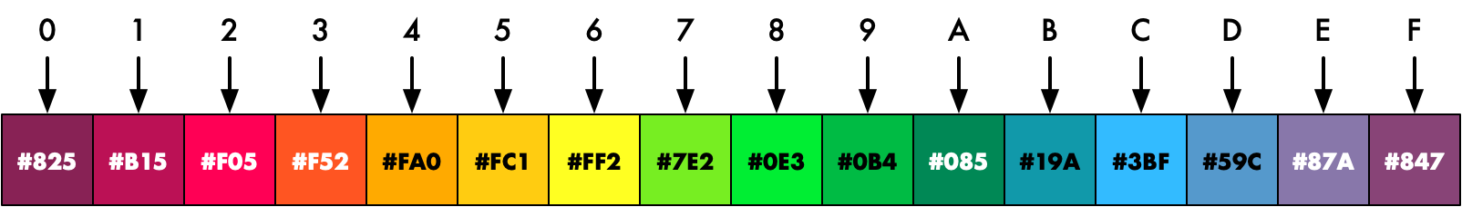
The hedgehog palette looks like this:

Next we make our hedgehog’s world a little more interesting by creating a landscape. We do this by with horizontal bars of colour in the background:
    // background colour
    logic [COLRW-1:0] bg_colr;
    always_ff @(posedge clk_pix) begin
        if (line) begin
            if      (sy == 0)   bg_colr <= 12'h239;
            else if (sy == 80)  bg_colr <= 12'h24A;
            else if (sy == 140) bg_colr <= 12'h25B;
            else if (sy == 190) bg_colr <= 12'h26C;
            else if (sy == 230) bg_colr <= 12'h27D;
            else if (sy == 265) bg_colr <= 12'h29E;
            else if (sy == 295) bg_colr <= 12'h2BF;
            else if (sy == 320) bg_colr <= 12'h260;
        end
    end
We move our hedgehog down the screen to walk on the ground:
    if (rst_pix) begin  // start off screen and level with grass
        sprx <= H_RES;
        spry <= 240;
    end
- iCEBreaker (iCE40): ice40/top_hedgehog.sv
- Arty (XC7): xc7/top_hedgehog.sv
- Nexys Video (XC7): xc7-dvi/top_hedgehog.sv
- Verilator Sim: sim/top_hedgehog.sv
Nexys Video version shown below:
module top_hedgehog (
    input  wire logic clk_100m,       // 100 MHz clock
    input  wire logic btn_rst_n,      // reset button
    output      logic hdmi_tx_ch0_p,  // HDMI source channel 0 diff+
    output      logic hdmi_tx_ch0_n,  // HDMI source channel 0 diff-
    output      logic hdmi_tx_ch1_p,  // HDMI source channel 1 diff+
    output      logic hdmi_tx_ch1_n,  // HDMI source channel 1 diff-
    output      logic hdmi_tx_ch2_p,  // HDMI source channel 2 diff+
    output      logic hdmi_tx_ch2_n,  // HDMI source channel 2 diff-
    output      logic hdmi_tx_clk_p,  // HDMI source clock diff+
    output      logic hdmi_tx_clk_n   // HDMI source clock diff-
    );

    // generate pixel clock
    logic clk_pix;
    logic clk_pix_5x;
    logic clk_pix_locked;
    logic rst_pix;
    clock_720p clock_pix_inst (
       .clk_100m,
       .rst(!btn_rst_n),  // reset button is active low
       .clk_pix,
       .clk_pix_5x,
       .clk_pix_locked
    );
    always_ff @(posedge clk_pix) rst_pix <= !clk_pix_locked;  // wait for clock lock

    // display sync signals and coordinates
    localparam CORDW = 16;  // signed coordinate width (bits)
    logic [CORDW-1:0] sx, sy;
    logic hsync, vsync;
    logic de, frame, line;
    display_720p #(.CORDW(CORDW)) display_inst (
        .clk_pix,
        .rst_pix,
        .sx,
        .sy,
        .hsync,
        .vsync,
        .de,
        .frame,
        .line
    );

    // screen dimensions (must match display_inst)
    localparam H_RES = 1280;

    // colour parameters
    localparam CHANW = 4;         // colour channel width (bits)
    localparam COLRW = 3*CHANW;   // colour width: three channels (bits)
    localparam CIDXW = 4;         // colour index width (bits)
    localparam TRANS_INDX = 'h9;  // transparant colour index
    localparam PAL_FILE = "hedgehog_4b.mem";  // palette file

    // sprite parameters
    localparam SX_OFFS    =  3;  // horizontal screen offset (pixels): +1 for CLUT
    localparam SPR_WIDTH  = 32;  // bitmap width in pixels
    localparam SPR_HEIGHT = 20;  // bitmap height in pixels
    localparam SPR_SCALE  =  3;  // 2^3 = 8x scale
    localparam SPR_DRAWW  = SPR_WIDTH * 2**SPR_SCALE;  // draw width
    localparam SPR_SPX    =  4;  // horizontal speed (pixels/frame)
    localparam SPR_FILE   = "hedgehog.mem";  // bitmap file

    logic signed [CORDW-1:0] sprx, spry;  // draw sprite at position (sprx,spry)

    // update sprite position once per frame
    always_ff @(posedge clk_pix) begin
        if (frame) begin
            if (sprx <= -SPR_DRAWW) sprx <= H_RES;  // move back to right of screen
            else sprx <= sprx - SPR_SPX;  // otherwise keep moving left
        end
        if (rst_pix) begin  // start off screen and level with grass
            sprx <= H_RES;
            spry <= 320;
        end
    end

    logic drawing;  // drawing at (sx,sy)
    logic [CIDXW-1:0] spr_pix_indx;  // pixel colour index
    sprite #(
        .CORDW(CORDW),
        .H_RES(H_RES),
        .SX_OFFS(SX_OFFS),
        .SPR_FILE(SPR_FILE),
        .SPR_WIDTH(SPR_WIDTH),
        .SPR_HEIGHT(SPR_HEIGHT),
        .SPR_SCALE(SPR_SCALE),
        .SPR_DATAW(CIDXW)
        ) sprite_hedgehog (
        .clk(clk_pix),
        .rst(rst_pix),
        .line,
        .sx,
        .sy,
        .sprx,
        .spry,
        .pix(spr_pix_indx),
        .drawing
    );

    // colour lookup table
    logic [COLRW-1:0] spr_pix_colr;
    clut_simple #(
        .COLRW(COLRW),
        .CIDXW(CIDXW),
        .F_PAL(PAL_FILE)
        ) clut_instance (
        .clk_write(clk_pix),
        .clk_read(clk_pix),
        .we(0),
        .cidx_write(0),
        .cidx_read(spr_pix_indx),
        .colr_in(0),
        .colr_out(spr_pix_colr)
    );

    // account for transparency and delay drawing signal to match CLUT delay (1 cycle)
    logic drawing_t1;
    always_ff @(posedge clk_pix) drawing_t1 <= drawing && (spr_pix_indx != TRANS_INDX);

    // background colour
    logic [COLRW-1:0] bg_colr;
    always_ff @(posedge clk_pix) begin
        if (line) begin
            if      (sy == 0)   bg_colr <= 12'h239;
            else if (sy == 120) bg_colr <= 12'h24A;
            else if (sy == 220) bg_colr <= 12'h25B;
            else if (sy == 300) bg_colr <= 12'h26C;
            else if (sy == 360) bg_colr <= 12'h27D;
            else if (sy == 410) bg_colr <= 12'h29E;
            else if (sy == 450) bg_colr <= 12'h2BF;
            else if (sy == 480) bg_colr <= 12'h260;
        end
    end

    // paint colour: sprite or background
    logic [CHANW-1:0] paint_r, paint_g, paint_b;
    always_comb {paint_r, paint_g, paint_b} = (drawing_t1) ? spr_pix_colr : bg_colr;

    // display colour: paint colour but black in blanking interval
    logic [CHANW-1:0] display_r, display_g, display_b;
    always_comb begin
        display_r = (de) ? paint_r : 4'h0;
        display_g = (de) ? paint_g : 4'h0;
        display_b = (de) ? paint_b : 4'h0;
    end

    // DVI signals (8 bits per colour channel)
    logic [2*CHANW-1:0] dvi_r, dvi_g, dvi_b;
    logic dvi_hsync, dvi_vsync, dvi_de;
    always_ff @(posedge clk_pix) begin
        dvi_hsync <= hsync;
        dvi_vsync <= vsync;
        dvi_de    <= de;
        dvi_r <= {2{display_r}};
        dvi_g <= {2{display_g}};
        dvi_b <= {2{display_b}};
    end

    // TMDS encoding and serialization
    logic tmds_ch0_serial, tmds_ch1_serial, tmds_ch2_serial, tmds_clk_serial;
    dvi_generator dvi_out (
        .clk_pix,
        .clk_pix_5x,
        .rst_pix,
        .de(dvi_de),
        .data_in_ch0(dvi_b),
        .data_in_ch1(dvi_g),
        .data_in_ch2(dvi_r),
        .ctrl_in_ch0({dvi_vsync, dvi_hsync}),
        .ctrl_in_ch1(2'b00),
        .ctrl_in_ch2(2'b00),
        .tmds_ch0_serial,
        .tmds_ch1_serial,
        .tmds_ch2_serial,
        .tmds_clk_serial
    );

    // TMDS output pins
    tmds_out tmds_ch0 (.tmds(tmds_ch0_serial),
        .pin_p(hdmi_tx_ch0_p), .pin_n(hdmi_tx_ch0_n));
    tmds_out tmds_ch1 (.tmds(tmds_ch1_serial),
        .pin_p(hdmi_tx_ch1_p), .pin_n(hdmi_tx_ch1_n));
    tmds_out tmds_ch2 (.tmds(tmds_ch2_serial),
        .pin_p(hdmi_tx_ch2_p), .pin_n(hdmi_tx_ch2_n));
    tmds_out tmds_clk (.tmds(tmds_clk_serial),
        .pin_p(hdmi_tx_clk_p), .pin_n(hdmi_tx_clk_n));
endmodule
Here’s our finished landscape with hedgehog:

Explore
I hope you enjoyed this instalment of Exploring FPGA Graphics, but nothing beats creating your own designs. Here are a few sprite suggestions:
- Design your own 8x8 spaceship sprite
- Use buttons to control the position of a sprite on screen
- Add additional hedgehogs sprite instances to the final design
- Draw the numbers 0-9 as sprites and use them to score Pong
Sprite Engine
This sprite design works for simple cases but lacks many desirable features for games. One day I plan to write about a sprite engine, including external memory, animated graphics, rotation, and collision detection.
What’s Next?
Next time in FPGA Graphics, we learn about framebuffers and bitmap graphics.