Display Signals
Welcome back to Exploring FPGA Graphics. Last time, we played Pong against our FPGA; this time, we revisit displays signals and learn about palettes and indexed colour.
In this series, we learn about graphics at the hardware level and get a feel for the power of FPGAs. We’ll learn how screens work, play Pong, create starfields and sprites, paint Michelangelo’s David, draw lines and triangles, and animate characters and shapes. New to the series? Start with Beginning FPGA Graphics.

Series Outline
- Beginning FPGA Graphics - video signals and basic graphics
- Racing the Beam - simple demo effects with minimal logic
- FPGA Pong - recreate the classic arcade on an FPGA
- Display Signals (this post) - revisit display signals and meet colour palettes
- Hardware Sprites - fast, colourful graphics for games
- Framebuffers - bitmap graphics featuring Michelangelo’s David
- Lines and Triangles - drawing lines and triangles
- 2D Shapes - filled shapes and simple pictures
- Animated Shapes - animation and double-buffering
Revisiting the Display
Didn’t we already sort out display signal generation at the start of the series? Yes, we did, but there are good reasons to change how we treat screen coordinates before we start drawing sprites.
The new signals module has several improvements at the cost of a little complexity:
- Blanking intervals occur before the active drawing area
- Signed coordinates for screen position
- Addition of frame and line signals
- Registered signals to improve timing
Take a look at the new [display_480p.sv] module, then we’ll discuss the changes in more detail:
module display_480p #(
    CORDW=16,    // signed coordinate width (bits)
    H_RES=640,   // horizontal resolution (pixels)
    V_RES=480,   // vertical resolution (lines)
    H_FP=16,     // horizontal front porch
    H_SYNC=96,   // horizontal sync
    H_BP=48,     // horizontal back porch
    V_FP=10,     // vertical front porch
    V_SYNC=2,    // vertical sync
    V_BP=33,     // vertical back porch
    H_POL=0,     // horizontal sync polarity (0:neg, 1:pos)
    V_POL=0      // vertical sync polarity (0:neg, 1:pos)
    ) (
    input  wire logic clk_pix,  // pixel clock
    input  wire logic rst_pix,  // reset in pixel clock domain
    output      logic hsync,    // horizontal sync
    output      logic vsync,    // vertical sync
    output      logic de,       // data enable (low in blanking interval)
    output      logic frame,    // high at start of frame
    output      logic line,     // high at start of line
    output      logic signed [CORDW-1:0] sx,  // horizontal screen position
    output      logic signed [CORDW-1:0] sy   // vertical screen position
    );

    // horizontal timings
    localparam signed H_STA  = 0 - H_FP - H_SYNC - H_BP;    // horizontal start
    localparam signed HS_STA = H_STA + H_FP;                // sync start
    localparam signed HS_END = HS_STA + H_SYNC;             // sync end
    localparam signed HA_STA = 0;                           // active start
    localparam signed HA_END = H_RES - 1;                   // active end

    // vertical timings
    localparam signed V_STA  = 0 - V_FP - V_SYNC - V_BP;    // vertical start
    localparam signed VS_STA = V_STA + V_FP;                // sync start
    localparam signed VS_END = VS_STA + V_SYNC;             // sync end
    localparam signed VA_STA = 0;                           // active start
    localparam signed VA_END = V_RES - 1;                   // active end

    logic signed [CORDW-1:0] x, y;  // screen position

    // generate horizontal and vertical sync with correct polarity
    always_ff @(posedge clk_pix) begin
        hsync <= H_POL ? (x >= HS_STA && x < HS_END) : ~(x >= HS_STA && x < HS_END);
        vsync <= V_POL ? (y >= VS_STA && y < VS_END) : ~(y >= VS_STA && y < VS_END);
        if (rst_pix) begin
            hsync <= H_POL ? 0 : 1;
            vsync <= V_POL ? 0 : 1;
        end
    end

    // control signals
    always_ff @(posedge clk_pix) begin
        de    <= (y >= VA_STA && x >= HA_STA);
        frame <= (y == V_STA  && x == H_STA);
        line  <= (x == H_STA);
        if (rst_pix) begin
            de <= 0;
            frame <= 0;
            line <= 0;
        end
    end

    // calculate horizontal and vertical screen position
    always_ff @(posedge clk_pix) begin
        if (x == HA_END) begin  // last pixel on line?
            x <= H_STA;
            y <= (y == VA_END) ? V_STA : y + 1;  // last line on screen?
        end else begin
            x <= x + 1;
        end
        if (rst_pix) begin
            x <= H_STA;
            y <= V_STA;
        end
    end

    // delay screen position to match sync and control signals
    always_ff @ (posedge clk_pix) begin
        sx <= x;
        sy <= y;
        if (rst_pix) begin
            sx <= H_STA;
            sy <= V_STA;
        end
    end
endmodule
Blanking First
The changes to blanking first and signed coordinates are linked.
Imagine we want to draw a sprite at the far-left of the screen. We need to start the drawing process before the first sprite pixel, for example, to load pixels from flash memory. If horizontal blanking occurs at the end of the line, we need to start the drawing process on the previous line. There is no prior line if we want to draw at the top of the screen, so we need to start during the last frame. Dealing with these edge cases complicates drawing needlessly.
If blanking the before active area is so handy, why didn’t we do this before? Putting the blanking interval first means the first visible pixel is no longer (0,0); for 640x480, it moves to (160,45). We can add an offset to all our positions, which is slightly annoying, but the Amiga successfully used this approach. However, this creates a new issue when using different resolutions: the Amiga worked around this by always using low-resolution sprite coordinates.
There is a better way if we’re prepared to accept signed coordinates. We retain (0,0) as the top-left of the visible screen, while blanking occurs at negative coordinates. If we adopt 16-bit signed coordinates, we can handle any plausible screen size and an (X,Y) coordinate pair fits cleanly into a 32-bit word. Signed signals are a bit of a pain in Verilog, but I’ve found the slight inconvenience more than worth it when working with sprites and framebuffers.
The following diagram shows the new display signals to scale with two 64x64 pixel squares drawn:

Frame Start, Line Start
In our new design, the start of a line or frame depends on the display timings. For example, with 640x480, a line begins at pixel -160 and a frame at line -45.
To avoid having to hard-code these values into designs, we create two new signals:
- frame - high for one tick at the start of a frame
- line - high for one tick at the start of a line
With these signals, you can safely link your logic to frames and lines, whatever the display mode.
Registered Signals
For simplicity, our original [simple_480p.sv] design had sync and data enable signals directly derived from sx and sy. However, it’s good practice to register module outputs: this maximises the time the module user has to work with.
Our improved design registers all outputs, which forces us to delay sx and sy to match; otherwise, the sync and control signals would be one cycle late. We use x and y internally and assign sx and sy from them.
A Refined Palette
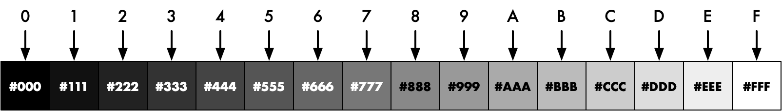
So far in this series, we’ve been using 12-bit colour values directly. For example, #137 is dark blue and #FFF is white.
However, using a full 12 bits for every pixel is wasteful for graphics with only a few colours.
To save resources, we can use fewer bits per pixel. The smallest we can get in RGB colour is 3 bits: one for each of red, green, and blue. However, this restricts us to eight fixed colours: black, red, green, yellow, blue, magenta, cyan, and white:

These eight colours were a fixture of 80s computers, including the BBC Micro and IBM PC CGA.
Indexed Colour
What we want is a few colours, but of our choosing. Using a little indirection, we can use few bits per pixel but with a full choice of colours.
Instead of each pixel storing the colour, we store an index. When we display a pixel, we look the index up in a table to find the colour to show. The table is a “colour lookup table” or CLUT.
Indexed colour was common in late 80s and early 90s computers, including the Amiga, Macintosh II, and IBM PC VGA. While most contemporary computers use 24-bit colour, PNG and GIF formats still use indexed colour to reduce file sizes.
With a 4-bit index, we can have 16 colours, but these can be any of our 4096 12-bit colours. I’ve shown a couple of sample palettes below:
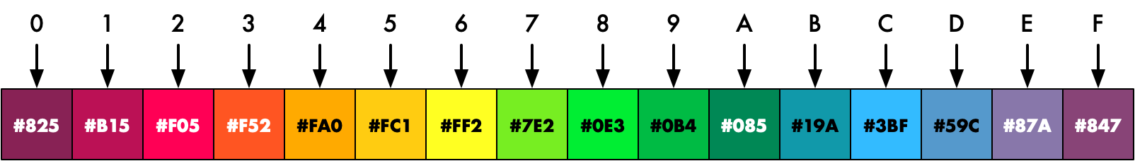
For example, if we set a pixel index to ‘3’, it would appear orange with the second palette.
CLUT Module
A CLUT needs a small amount of fast memory, for which block ram is ideal. I’ve designed a simple CLUT module using a single BRAM [clut_simple.sv]:
module clut_simple #(
    parameter COLRW=12,  // colour output width (bits)
    parameter CIDXW=4,   // colour index width (bits)
    parameter F_PAL=""   // init file for colour palette
    ) (
    input  wire logic clk_write,  // write clock
    input  wire logic clk_read,   // read clock
    input  wire logic we,         // write enable
    input  wire logic [CIDXW-1:0] cidx_write,  // colour index to write
    input  wire logic [CIDXW-1:0] cidx_read,   // colour index to read
    input  wire logic [COLRW-1:0] colr_in,     // write colour
    output      logic [COLRW-1:0] colr_out     // read colour
    );

    bram_sdp #(
        .WIDTH(COLRW),
        .DEPTH(2**CIDXW),
        .INIT_F(F_PAL)
        ) bram_clut (
        .clk_write,
        .clk_read,
        .we,
        .addr_write(cidx_write),
        .addr_read(cidx_read),
        .data_in(colr_in),
        .data_out(colr_out)
    );
endmodule
Palette Files
You can set the colours directly in logic, but loading an initial palette from a file is common. Our module supports this using the F_PAL parameter. The Project F Verilog Library includes several ready-to-use palettes in $readmemh format: [lib/res/palettes].
What’s Next?
Next time in FPGA Graphics, we’ll put our new display signals and colour palette to the test, generating fast, colourful graphics in Hardware Sprites.