Framebuffers
Welcome back to Exploring FPGA Graphics. In the previous part, we worked with sprites, but another approach is needed as graphics become more complex. Instead of drawing directly to the screen, we draw to a bitmap, which is read out to the screen. This post provides an introduction to framebuffers and how to scale them up. We’ll also learn how to fizzlefade graphics Wolfenstein 3D style.
In this series, we learn about graphics at the hardware level and get a feel for the power of FPGAs. We’ll learn how screens work, play Pong, create starfields and sprites, paint Michelangelo’s David, draw lines and triangles, and animate characters and shapes. New to the series? Start with Beginning FPGA Graphics.

Series Outline
- Beginning FPGA Graphics - video signals and basic graphics
- Racing the Beam - simple demo effects with minimal logic
- FPGA Pong - recreate the classic arcade on an FPGA
- Display Signals - revisit display signals and meet colour palettes
- Hardware Sprites - fast, colourful graphics for games
- Framebuffers (this post) - bitmap graphics featuring Michelangelo’s David
- Lines and Triangles - drawing lines and triangles
- 2D Shapes - filled shapes and simple pictures
- Animated Shapes - animation and double-buffering
Requirements
You should be to run these designs on any recent FPGA board. I include everything you need for the iCEBreaker with 12-Bit DVI Pmod, Digilent Arty A7-35T with Pmod VGA, Digilent Nexys Video with on-board HDMI output, and Verilator Simulation with SDL. See requirements from Beginning FPGA Graphics for more details.
Framebuffer
A framebuffer is an in-memory bitmap that drives pixels on the screen. When you write to a memory location within the framebuffer, the corresponding pixel will change on the screen. Using a framebuffer provides two big benefits: we’re free to create sophisticated graphics using whatever technique we like, and the setting of pixel colour is separated from the process of driving the screen. The flexibility of a framebuffer comes at the cost of increased memory use.
A Little Buffer
A framebuffer requires enough memory to hold the complete frame. To keep things simple, we’ll store our framebuffer in internal FPGA block memory (BRAM). The iCEBreaker’s iCE40 FPGA is the smallest, with 120 kb of BRAM, so that’s what we’ll target.
If we divide our 640x480 screen by four, we get 160x120 (19,200 pixels):
- 2 colours need one bit per pixel - buffer size 19,200 bits (18.75 kb)
- 16 colours need four bits per pixel - buffer size 76,800 bits (75 kb)
A Little Bitmap

A small monochrome framebuffer calls for a striking image: I’ve chosen David by Michelangelo.
The version on the right is the original from Wikipedia; it has 64 shades of grey. I created the middle image by reducing the original to 16 colours using img2fmem with no dithering (we’ll discuss this tool later). The monochrome image on the left was created by Gerbrant using Floyd-Steinberg dithering.
David Mono
Our first example loads a monochrome image of David into the framebuffer and displays it on screen. We use the same display signal and video output design from previous posts.
- iCEBreaker (iCE40): ice40/top_david_mono.sv
- Arty (XC7): xc7/top_david_mono.sv
- Nexys Video (XC7): xc7-dvi/top_david_mono.sv
- Verilator Sim: sim/top_david_mono.sv
Arty version:
module top_david_mono (
    input  wire logic clk_100m,     // 100 MHz clock
    input  wire logic btn_rst_n,    // reset button
    output      logic vga_hsync,    // horizontal sync
    output      logic vga_vsync,    // vertical sync
    output      logic [3:0] vga_r,  // 4-bit VGA red
    output      logic [3:0] vga_g,  // 4-bit VGA green
    output      logic [3:0] vga_b   // 4-bit VGA blue
    );

    // generate pixel clock
    logic clk_pix;
    logic clk_pix_locked;
    logic rst_pix;
    clock_480p clock_pix_inst (
       .clk_100m,
       .rst(!btn_rst_n),  // reset button is active low
       .clk_pix,
       .clk_pix_5x(),  // not used for VGA output
       .clk_pix_locked
    );
    always_ff @(posedge clk_pix) rst_pix <= !clk_pix_locked;  // wait for clock lock

    // display sync signals and coordinates
    localparam CORDW = 16;  // signed coordinate width (bits)
    logic signed [CORDW-1:0] sx, sy;
    logic hsync, vsync;
    logic de, frame;
    display_480p #(.CORDW(CORDW)) display_inst (
        .clk_pix,
        .rst_pix,
        .sx,
        .sy,
        .hsync,
        .vsync,
        .de,
        .frame,
        .line()
    );

    // colour parameters
    localparam CHANW = 4;        // colour channel width (bits)
    localparam COLRW = 3*CHANW;  // colour width: three channels (bits)
    localparam BG_COLR = 'h137;  // background colour

    // framebuffer (FB)
    localparam FB_WIDTH  = 160;  // framebuffer width in pixels
    localparam FB_HEIGHT = 120;  // framebuffer width in pixels
    localparam FB_PIXELS = FB_WIDTH * FB_HEIGHT;  // total pixels in buffer
    localparam FB_ADDRW  = $clog2(FB_PIXELS);  // address width
    localparam FB_DATAW  = 1;  // colour bits per pixel
    localparam FB_IMAGE  = "david_1bit.mem";  // bitmap file
    // localparam FB_IMAGE  = "test_box_mono_160x120.mem";  // bitmap file

    // pixel read address and colour
    logic [FB_ADDRW-1:0] fb_addr_read;
    logic [FB_DATAW-1:0] fb_colr_read;

    // framebuffer memory
    bram_sdp #(
        .WIDTH(FB_DATAW),
        .DEPTH(FB_PIXELS),
        .INIT_F(FB_IMAGE)
    ) bram_inst (
        .clk_write(clk_pix),
        .clk_read(clk_pix),
        .we(),
        .addr_write(),
        .addr_read(fb_addr_read),
        .data_in(),
        .data_out(fb_colr_read)
    );

    // calculate framebuffer read address for display output
    localparam LAT = 2;  // read_fb+1, BRAM+1
    logic read_fb;
    always_ff @(posedge clk_pix) begin
        read_fb <= (sy >= 0 && sy < FB_HEIGHT && sx >= -LAT && sx < FB_WIDTH-LAT);
        if (frame) begin  // reset address at start of frame
            fb_addr_read <= 0;
        end else if (read_fb) begin  // increment address in painting area
            fb_addr_read <= fb_addr_read + 1;
        end
    end

    // paint screen
    logic paint_area;  // area of framebuffer to paint
    logic [CHANW-1:0] paint_r, paint_g, paint_b;  // colour channels
    always_comb begin
        paint_area = (sy >= 0 && sy < FB_HEIGHT && sx >= 0 && sx < FB_WIDTH);
        {paint_r, paint_g, paint_b} = paint_area ? {COLRW{fb_colr_read}} : BG_COLR;
    end

    // display colour: paint colour but black in blanking interval
    logic [CHANW-1:0] display_r, display_g, display_b;
    always_comb {display_r, display_g, display_b} = (de) ? {paint_r, paint_g, paint_b} : 0;

    // VGA Pmod output
    always_ff @(posedge clk_pix) begin
        vga_hsync <= hsync;
        vga_vsync <= vsync;
        vga_r <= display_r;
        vga_g <= display_g;
        vga_b <= display_b;
    end
endmodule
Building the Designs
In the Framebuffers section of the git repo, you’ll find the design files, a makefile for iCEBreaker and Verilator, and a Vivado project for Xilinx-based boards. There are also build instructions for boards and simulations.
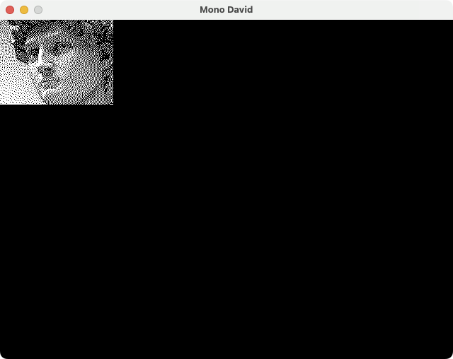
Build mono David for your board or the Verilator sim. You should see a small dithered David looking at you from the top-left of the screen.
NB. You can safely ignore Vivado get/set clock warnings. The XDC constraints file contains settings for designs we’ll discuss later in this post.
The Verilator sim looks like this:
Framebuffer Memory
The core of the framebuffer design is the memory. We use parameters to set the bitmap dimensions and colour bits, determining our buffer’s depth and address width.
    // framebuffer (FB)
    localparam FB_WIDTH  = 160;  // framebuffer width in pixels
    localparam FB_HEIGHT = 120;  // framebuffer width in pixels
    localparam FB_PIXELS = FB_WIDTH * FB_HEIGHT;  // total pixels in buffer
    localparam FB_ADDRW  = $clog2(FB_PIXELS);  // address width
    localparam FB_DATAW  = 1;  // colour bits per pixel
    localparam FB_IMAGE  = "david_1bit.mem";  // bitmap file
    // localparam FB_IMAGE  = "test_box_mono_160x120.mem";  // bitmap file

    // pixel read address and colour
    logic [FB_ADDRW-1:0] fb_addr_read;
    logic [FB_DATAW-1:0] fb_colr_read;

    // framebuffer memory
    bram_sdp #(
        .WIDTH(FB_DATAW),
        .DEPTH(FB_PIXELS),
        .INIT_F(FB_IMAGE)
    ) bram_inst (
        .clk_write(clk_pix),
        .clk_read(clk_pix),
        .we(),
        .addr_write(),
        .addr_read(fb_addr_read),
        .data_in(),
        .data_out(fb_colr_read)
    );
You can find the BRAM module in the Verilog library: [lib/memory/bram_sdp.sv]. This simple module infers block ram without you having to worry about the low-level implementation details.
The memory design has read and write ports, but we only read for mono David. The bitmap image of David is loaded into BRAM as part of the initial FPGA device configuration.
We store the bitmap in a text file [res/david/david_1bit.mem]:
// Project F: Framebuffers - David 160x120 Image (Monochrome)
// Learn more at https://projectf.io/posts/framebuffers/
1
0
1
1
0
1
....
Time to Read
We have our image in memory; we just need to know when to read and display each pixel.
Your first thought might be to calculate the memory address directly from the screen coordinates, such as: fb_addr_read = sy * FB_WIDTH + sx. While superficially appealing, this approach ties the memory clock directly to the pixel clock, limiting our flexibility and efficiency. How would we handle memory latency? How would we share memory access with a CPU?
A better approach is to increment the memory address every time we need to read a pixel. No multiplication is required, and we can easily compensate for any latency:
    // calculate framebuffer read address for display output
    localparam LAT = 2;  // read_fb+1, BRAM+1
    logic read_fb;
    always_ff @(posedge clk_pix) begin
        read_fb <= (sy >= 0 && sy < FB_HEIGHT && sx >= -LAT && sx < FB_WIDTH-LAT);
        if (frame) begin  // reset address at start of frame
            fb_addr_read <= 0;
        end else if (read_fb) begin  // increment address in painting area
            fb_addr_read <= fb_addr_read + 1;
        end
    end
We define the screen area we want to paint using the screen position (sx,sy) and the framebuffer height FB_HEIGHT and width FB_WIDTH. But we subtract the latency LAT from the horizontal position: one cycle allows for the calculation of read_fb and one cycle for the BRAM to return the data.
In this example, with LAT = 2, the comparisons are sx >= -2 and sx < 158.
Latency Testing
It’s easy to overlook latency in your design, rendering your framebuffer off by one or two pixels. To get the design right, I’ve created a test image, test_box_mono_160x120.mem. The test image draws a single pixel around the edge of the framebuffer, making it straightforward to spot errors.
Try test_box_mono with different values for LAT; notice how the rendering of the box changes. If the image is too small to see clearly, don’t worry, we’ll be scaling it up shortly.
Painting the Screen
Using the pixel data from the framebuffer, we can decide when to draw a white pixel 12'hFFF and when to draw black 12'h000. Feel free to try your own colours.
    // paint screen
    logic paint_area;  // area of framebuffer to paint
    logic [CHANW-1:0] paint_r, paint_g, paint_b;  // colour channels
    always_comb begin
        paint_area = (sy >= 0 && sy < FB_HEIGHT && sx >= 0 && sx < FB_WIDTH);
        {paint_r, paint_g, paint_b} = paint_area ? {COLRW{fb_colr_read}} : BG_COLR;
    end
Combinational Painting?
We use combinational logic here to avoid latency correction on the display signals, such ash_sync. The design still easily passes timing, so I think this simplification is worthwhile.
David Grey
If we increase the number of bits per pixel to four, we can have 16 colours (or shades of grey). We store the colour index for each pixel and then look the colour up in a colour lookup table. We previously discussed colour lookup tables and indexed colour in Display Signals.
- iCEBreaker (iCE40): ice40/top_david_16colr.sv
- Arty (XC7): xc7/top_david_16colr.sv
- Nexys Video (XC7): xc7-dvi/top_david_16colr.sv
- Verilator Sim: sim/top_david_16colr.sv
The changed part of the design is shown below for Arty (other boards are very similar):
    // bitmap images
    localparam BMAP_IMAGE = "david.mem";
    // localparam BMAP_IMAGE = "test_box_160x120.mem";

    // colour palettes
    localparam PAL_FILE = "grey16_4b.mem";
    // localparam PAL_FILE = "greyinvert16_4b.mem";
    // localparam PAL_FILE = "sepia16_4b.mem";
    // localparam PAL_FILE = "sweetie16_4b.mem";

    // colour parameters
    localparam CHANW = 4;        // colour channel width (bits)
    localparam COLRW = 3*CHANW;  // colour width: three channels (bits)
    localparam CIDXW = 4;        // colour index width (bits)
    localparam BG_COLR = 'h137;  // background colour

    // framebuffer (FB)
    localparam FB_WIDTH  = 160;  // framebuffer width in pixels
    localparam FB_HEIGHT = 120;  // framebuffer width in pixels
    localparam FB_PIXELS = FB_WIDTH * FB_HEIGHT;  // total pixels in buffer
    localparam FB_ADDRW  = $clog2(FB_PIXELS);  // address width
    localparam FB_DATAW  = CIDXW;  // colour bits per pixel

    // pixel read address and colour
    logic [FB_ADDRW-1:0] fb_addr_read;
    logic [FB_DATAW-1:0] fb_colr_read;

    // framebuffer memory
    bram_sdp #(
        .WIDTH(FB_DATAW),
        .DEPTH(FB_PIXELS),
        .INIT_F(BMAP_IMAGE)
    ) bram_inst (
        .clk_write(clk_pix),
        .clk_read(clk_pix),
        .we(),
        .addr_write(),
        .addr_read(fb_addr_read),
        .data_in(),
        .data_out(fb_colr_read)
    );

    // calculate framebuffer read address for display output
    localparam LAT = 3;  // read_fb+1, BRAM+1, CLUT+1
    logic read_fb;
    always_ff @(posedge clk_pix) begin
        read_fb <= (sy >= 0 && sy < FB_HEIGHT && sx >= -LAT && sx < FB_WIDTH-LAT);
        if (frame) begin  // reset address at start of frame
            fb_addr_read <= 0;
        end else if (read_fb) begin  // increment address in painting area
            fb_addr_read <= fb_addr_read + 1;
        end
    end

    // colour lookup table
    logic [COLRW-1:0] fb_pix_colr;
    clut_simple #(
        .COLRW(COLRW),
        .CIDXW(CIDXW),
        .F_PAL(PAL_FILE)
        ) clut_instance (
        .clk_write(clk_pix),
        .clk_read(clk_pix),
        .we(0),
        .cidx_write(0),
        .cidx_read(fb_colr_read),
        .colr_in(0),
        .colr_out(fb_pix_colr)
    );

    // paint screen
    logic paint_area;  // area of framebuffer to paint
    logic [CHANW-1:0] paint_r, paint_g, paint_b;  // colour channels
    always_comb begin
        paint_area = (sy >= 0 && sy < FB_HEIGHT && sx >= 0 && sx < FB_WIDTH);
        {paint_r, paint_g, paint_b} = paint_area ? fb_pix_colr : BG_COLR;
    end
Looking up a colour in the colour lookup table takes a clock cycle, so we compensate by increasing the latency LAT to three cycles.
You can use the coloured test image test_box_160x120.mem to check for latency issues; it works best with the sweetie16_4b.mem colour palette.
Colour Me In
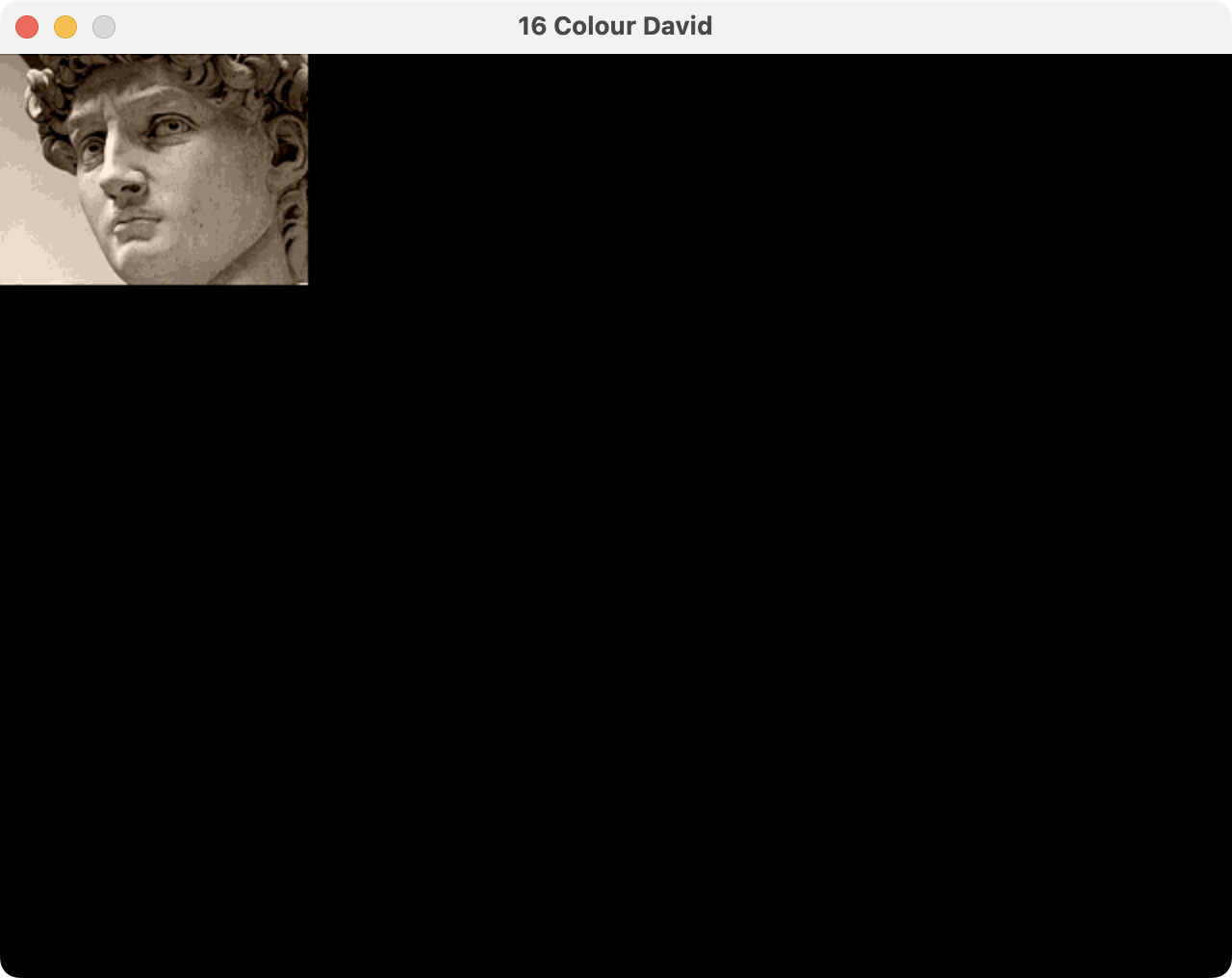
Try changing PAL_FILE to select one of the other palettes: I’ve included four in the design.
With the sepia16_4b palette, the simulation looks like this:
Scaling
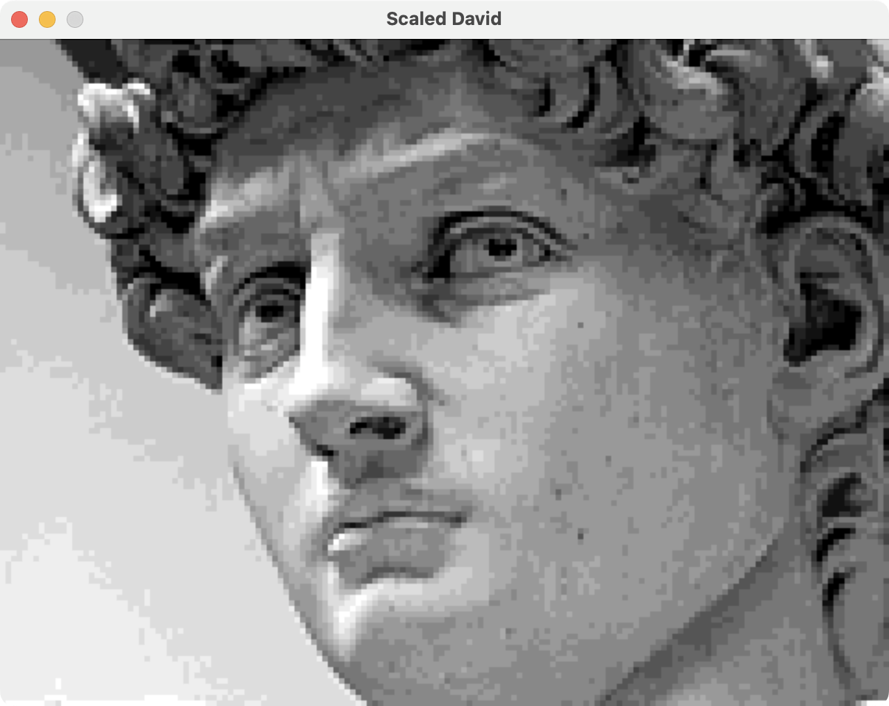
Our David is disappointingly small: we want him to fill the screen. Not only that, but we want to scale him up while retaining our efficient memory access. To accomplish this, we’ll introduce a linebuffer and cross clock domains.
Linebuffer
Scaling our 160x120 framebuffer up to 640x480 renders each pixel 16 times. Scaling up repeats pixels, but we don’t want to repeat memory access.
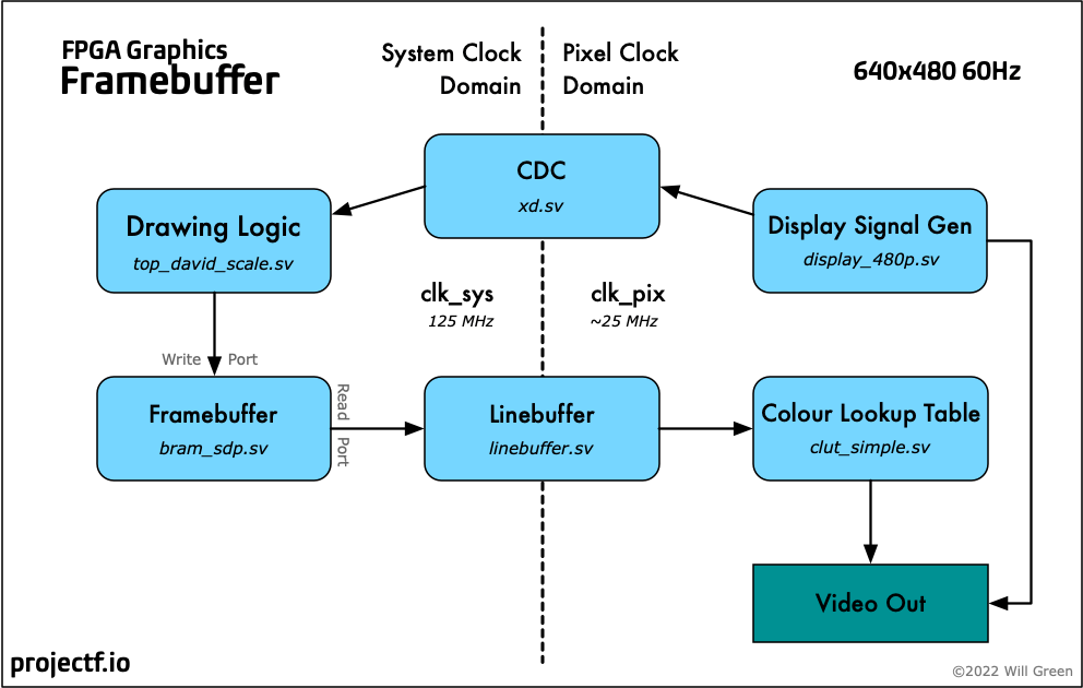
Instead of sending pixels directly from the framebuffer to the screen, we load each line into a linebuffer. Each pixel is read into the linebuffer once per frame but displayed as many times as needed. The linebuffer memory is read many times for each pixel, but it’s small and dedicated to the task.
The linebuffer provides a second valuable service: using a dual-port BRAM, we can support two clocks: system and pixel. We read data into the linebuffer at the system clock but output for display at the pixel clock. Separate clocks improve performance and allow the system clock to remain constant when we change the display resolution. We discuss the clocks in more detail below.
Linebuffer Module
The linebuffer module is based on a simple dual-port BRAM [linebuffer_simple.sv]:
module linebuffer_simple #(
    parameter DATAW=4,  // data width of each channel
    parameter LEN=640,  // length of line
    parameter SCALEW=6  // scale width (max scale == 2^SCALEW-1)
    ) (
    input  wire logic clk_sys,   // input clock
    input  wire logic clk_pix,   // output clock
    input  wire logic line,      // line start (clk_pix)
    input  wire logic line_sys,  // line start (clk_sys)
    input  wire logic en_in,     // enable input (clk_sys)
    input  wire logic en_out,    // enable output (clk_pix)
    input  wire logic [SCALEW-1:0] scale,   // scale factor (>=1)
    input  wire logic [DATAW-1:0] data_in,  // data in (clk_sys)
    output      logic [DATAW-1:0] data_out  // data out (clk_pix)
    );

    // output data
    logic [$clog2(LEN)-1:0] addr_out;  // output address (pixel counter)
    logic [SCALEW-1:0] cnt_h;  // horizontal scale counter
    always_ff @(posedge clk_pix) begin
        if (en_out) begin
            if (cnt_h == scale-1) begin
                cnt_h <= 0;
                if (addr_out != LEN-1) addr_out <= addr_out + 1;
            end else cnt_h <= cnt_h + 1;
        end
        if (line) begin
            addr_out <= 0;
            cnt_h <= 0;
        end
    end

    // read data in
    logic [$clog2(LEN)-1:0] addr_in;
    logic we;
    always_ff @(posedge clk_sys) begin
        if (en_in) we <= 1;
        if (addr_in == LEN-1) we <= 0;
        if (we) addr_in <= addr_in + 1;
        if (line_sys) begin
            we <= 0;
            addr_in <= 0;
        end
    end

    bram_sdp #(
        .WIDTH(DATAW),
        .DEPTH(LEN)
        ) bram_lb (
        .clk_write(clk_sys),
        .clk_read(clk_pix),
        .we,
        .addr_write(addr_in),
        .addr_read(addr_out),
        .data_in,
        .data_out
    );
endmodule
The linebuffer doesn’t know anything about the source or destination of the data. When en_in is high, it reads from data_in. When en_out is high, it writes to data_out. The line and line_sys signals reset the internal BRAM read and write addresses, respectively.
The linebuffer handles horizontal scaling by repeating an output pixel scale times. Vertical scaling is handled by the driving top module, discussed below.
Clocks
For the Arty board, we can run most of the scaled design (including the framebuffer) at 125 MHz while the display output continues at 25.2 MHz. To generate a 125 MHz system clock we use another clock generation module: [xc7/clock_sys.sv].
The system clock instance in the top module looks like this (complete with reset signal):
// generate system clock
logic clk_sys;
logic clk_sys_locked;
logic rst_sys;
clock_sys clock_sys_inst (
    .clk_100m,
    .rst(!btn_rst_n),  // reset button is active low
    .clk_sys,
    .clk_sys_locked
);
always_ff @(posedge clk_sys) rst_sys <= !clk_sys_locked;  // wait for clock lock
The iCEBreaker has only one PLL, so we make the system clock the same as the pixel clock:
// system clock is the same as pixel clock on iCE40
logic clk_sys, rst_sys;
always_comb begin
    clk_sys = clk_pix;
    rst_sys = rst_pix;
end
Keeping the system clock around makes it simpler to share designs between boards.
Crossing Clock Domains
The linebuffer handles the pixels, but we also need display signals in the system clock domain, such as frame start. The display signals are isolated single pulses, so we can send them across domains with the xd module. See the library post on xd for details of this module.
The display module generates the frame signal in the pixel clock domain clk_pix.
We make it available in the system clock domain clk_sys like this:
logic frame_sys;
xd xd_frame (.clk_src(clk_pix),.clk_dst(clk_sys), .flag_src(frame), .flag_dst(frame_sys));
Scaled Design
Adding the linebuffer with scaling gives us a full-screen David:
- iCEBreaker (iCE40): ice40/top_david_scale.sv
- Arty (XC7): xc7/top_david_scale.sv
- Nexys Video (XC7): xc7-dvi/top_david_scale.sv
- Verilator Sim: sim/top_david_scale.sv
Arty version:
module top_david_scale (
    input  wire logic clk_100m,     // 100 MHz clock
    input  wire logic btn_rst_n,    // reset button
    output      logic vga_hsync,    // horizontal sync
    output      logic vga_vsync,    // vertical sync
    output      logic [3:0] vga_r,  // 4-bit VGA red
    output      logic [3:0] vga_g,  // 4-bit VGA green
    output      logic [3:0] vga_b   // 4-bit VGA blue
    );

    // generate system clock
    logic clk_sys;
    logic clk_sys_locked;
    logic rst_sys;
    clock_sys clock_sys_inst (
       .clk_100m,
       .rst(!btn_rst_n),  // reset button is active low
       .clk_sys,
       .clk_sys_locked
    );
    always_ff @(posedge clk_sys) rst_sys <= !clk_sys_locked;  // wait for clock lock

    // generate pixel clock
    logic clk_pix;
    logic clk_pix_locked;
    logic rst_pix;
    clock_480p clock_pix_inst (
       .clk_100m,
       .rst(!btn_rst_n),  // reset button is active low
       .clk_pix,
       .clk_pix_5x(),  // not used for VGA output
       .clk_pix_locked
    );
    always_ff @(posedge clk_pix) rst_pix <= !clk_pix_locked;  // wait for clock lock

    // display sync signals and coordinates
    localparam CORDW = 16;  // signed coordinate width (bits)
    logic signed [CORDW-1:0] sx, sy;
    logic hsync, vsync;
    logic de, frame, line;
    display_480p #(.CORDW(CORDW)) display_inst (
        .clk_pix,
        .rst_pix,
        .sx,
        .sy,
        .hsync,
        .vsync,
        .de,
        .frame,
        .line
    );

    // bitmap images
    localparam BMAP_IMAGE = "david.mem";
    // localparam BMAP_IMAGE = "test_box_160x120.mem";

    // colour palettes
    localparam PAL_FILE = "grey16_4b.mem";
    // localparam PAL_FILE = "greyinvert16_4b.mem";
    // localparam PAL_FILE = "sepia16_4b.mem";
    // localparam PAL_FILE = "sweetie16_4b.mem";

    // colour parameters
    localparam CHANW = 4;        // colour channel width (bits)
    localparam COLRW = 3*CHANW;  // colour width: three channels (bits)
    localparam CIDXW = 4;        // colour index width (bits)
    localparam BG_COLR = 'h137;  // background colour

    // framebuffer (FB)
    localparam FB_WIDTH  = 160;  // framebuffer width in pixels
    localparam FB_HEIGHT = 120;  // framebuffer height in pixels
    localparam FB_SCALE  =   4;  // framebuffer display scale (1-63)
    localparam FB_PIXELS = FB_WIDTH * FB_HEIGHT;  // total pixels in buffer
    localparam FB_ADDRW  = $clog2(FB_PIXELS);  // address width
    localparam FB_DATAW  = CIDXW;  // colour bits per pixel

    // pixel read address and colour
    logic [FB_ADDRW-1:0] fb_addr_read;
    logic [FB_DATAW-1:0] fb_colr_read;

    // framebuffer memory
    bram_sdp #(
        .WIDTH(FB_DATAW),
        .DEPTH(FB_PIXELS),
        .INIT_F(BMAP_IMAGE)
    ) bram_inst (
        .clk_write(clk_sys),
        .clk_read(clk_sys),
        .we(),
        .addr_write(),
        .addr_read(fb_addr_read),
        .data_in(),
        .data_out(fb_colr_read)
    );

    // display flags in system clock domain
    logic frame_sys, line_sys, line0_sys;
    xd xd_frame (.clk_src(clk_pix), .clk_dst(clk_sys),
        .flag_src(frame), .flag_dst(frame_sys));
    xd xd_line  (.clk_src(clk_pix), .clk_dst(clk_sys),
        .flag_src(line),  .flag_dst(line_sys));
    xd xd_line0 (.clk_src(clk_pix), .clk_dst(clk_sys),
        .flag_src(line && sy==0), .flag_dst(line0_sys));

    // count lines for scaling via linebuffer
    logic [$clog2(FB_SCALE):0] cnt_lb_line;
    always_ff @(posedge clk_sys) begin
        if (line0_sys) cnt_lb_line <= 0;
        else if (line_sys) begin
            cnt_lb_line <= (cnt_lb_line == FB_SCALE-1) ? 0 : cnt_lb_line + 1;
        end
    end

    // which screen lines need linebuffer?
    logic lb_line;
    always_ff @(posedge clk_sys) begin
        if (line0_sys) lb_line <= 1;  // enable from sy==0
        if (frame_sys) lb_line <= 0;  // disable at frame start
    end

    // enable linebuffer input
    logic lb_en_in;
    logic [$clog2(FB_WIDTH)-1:0] cnt_lbx;  // horizontal pixel counter
    always_comb lb_en_in = (lb_line && cnt_lb_line == 0 && cnt_lbx < FB_WIDTH);

    // calculate framebuffer read address for linebuffer
    always_ff @(posedge clk_sys) begin
        if (line_sys) begin  // reset horizontal counter at start of line
            cnt_lbx <= 0;
        end else if (lb_en_in) begin  // increment address when LB enabled
            fb_addr_read <= fb_addr_read + 1;
            cnt_lbx <= cnt_lbx + 1;
        end
        if (frame_sys) fb_addr_read <= 0;  // reset address at frame start
    end

    // enable linebuffer output
    logic lb_en_out;
    localparam LAT_LB = 3;  // output latency compensation: lb_en_out+1, LB+1, CLUT+1
    always_ff @(posedge clk_pix) begin
        lb_en_out <= (sy >= 0 && sy < (FB_HEIGHT * FB_SCALE)
            && sx >= -LAT_LB && sx < (FB_WIDTH * FB_SCALE) - LAT_LB);
    end

    // display linebuffer
    logic [FB_DATAW-1:0] lb_colr_out;
    linebuffer_simple #(
        .DATAW(FB_DATAW),
        .LEN(FB_WIDTH)
    ) linebuffer_instance (
        .clk_sys,
        .clk_pix,
        .line,
        .line_sys,
        .en_in(lb_en_in),
        .en_out(lb_en_out),
        .scale(FB_SCALE),
        .data_in(fb_colr_read),
        .data_out(lb_colr_out)
    );

    // colour lookup table (CLUT)
    logic [COLRW-1:0] fb_pix_colr;
    clut_simple #(
        .COLRW(COLRW),
        .CIDXW(CIDXW),
        .F_PAL(PAL_FILE)
        ) clut_instance (
        .clk_write(clk_pix),
        .clk_read(clk_pix),
        .we(0),
        .cidx_write(0),
        .cidx_read(lb_colr_out),
        .colr_in(0),
        .colr_out(fb_pix_colr)
    );

    // paint screen
    logic paint_area;  // area of screen to paint
    logic [CHANW-1:0] paint_r, paint_g, paint_b;  // colour channels
    always_comb begin
        paint_area = (sy >= 0 && sy < (FB_HEIGHT * FB_SCALE)
            && sx >= 0 && sx < FB_WIDTH * FB_SCALE);
        {paint_r, paint_g, paint_b} = paint_area ? fb_pix_colr : BG_COLR;
    end

    // display colour: paint colour but black in blanking interval
    logic [CHANW-1:0] display_r, display_g, display_b;
    always_comb {display_r, display_g, display_b} = (de) ? {paint_r, paint_g, paint_b} : 0;

    // VGA Pmod output
    always_ff @(posedge clk_pix) begin
        vga_hsync <= hsync;
        vga_vsync <= vsync;
        vga_r <= display_r;
        vga_g <= display_g;
        vga_b <= display_b;
    end
endmodule
The linebuffer handles horizontal scaling for us, but we need to keep track of the vertical lines for vertical scaling. For every FB_SCALE lines in the visible part of the frame, we load a fresh line of pixels from the framebuffer into the linebuffer. line0_sys is the first visible line in the frame.
Fade Away
So far, we’ve only read our image: we’ve not made any changes to it. If we randomly write to every pixel, the image of David will fade away. We use a linear-feedback shift register (LFSR) to select the random pixels. You can learn about linear-feedback shift registers from my demo Ad Astra, where they’re used to generate animated starfields.
This effect is known as fizzlefade in Wolfenstein 3D. Fabien Sanglard discusses the original id Software implementation in Fizzlefade.
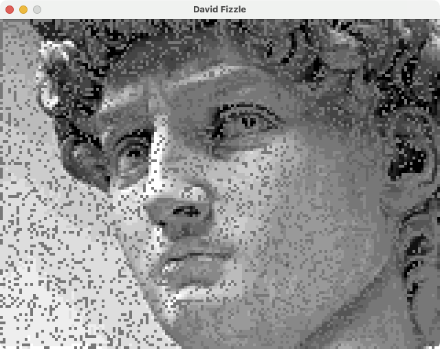
- iCEBreaker (iCE40): ice40/top_david_fizzle.sv
- Arty (XC7): xc7/top_david_fizzle.sv
- Nexys Video (XC7): xc7-dvi/top_david_fizzle.sv
- Verilator Sim: sim/top_david_fizzle.sv
The iCEBreaker version looks like this:
module top_david_fizzle (
    input  wire logic clk_12m,      // 12 MHz clock
    input  wire logic btn_rst,      // reset button
    output      logic dvi_clk,      // DVI pixel clock
    output      logic dvi_hsync,    // DVI horizontal sync
    output      logic dvi_vsync,    // DVI vertical sync
    output      logic dvi_de,       // DVI data enable
    output      logic [3:0] dvi_r,  // 4-bit DVI red
    output      logic [3:0] dvi_g,  // 4-bit DVI green
    output      logic [3:0] dvi_b   // 4-bit DVI blue
    );

    // system clock is the same as pixel clock on iCE40
    logic clk_sys, rst_sys;
    always_comb begin
        clk_sys = clk_pix;
        rst_sys = rst_pix;
    end

    // generate pixel clock
    logic clk_pix;
    logic clk_pix_locked;
    clock_480p clock_pix_inst (
       .clk_12m,
       .rst(btn_rst),
       .clk_pix,
       .clk_pix_locked
    );

    // reset in pixel clock domain
    logic rst_pix;
    always_comb rst_pix = !clk_pix_locked;  // wait for clock lock

    // display sync signals and coordinates
    localparam CORDW = 16;  // signed coordinate width (bits)
    logic signed [CORDW-1:0] sx, sy;
    logic hsync, vsync;
    logic de, frame, line;
    display_480p #(.CORDW(CORDW)) display_inst (
        .clk_pix,
        .rst_pix,
        .sx,
        .sy,
        .hsync,
        .vsync,
        .de,
        .frame,
        .line
    );

    // library resource path
    localparam LIB_RES = "../../../lib/res";

    // bitmap images
    localparam BMAP_IMAGE = "../res/david/david.mem";
    // localparam BMAP_IMAGE = {LIB_RES,"/test/test_box_160x120.mem"};

    // colour palettes
    localparam PAL_FILE = {LIB_RES,"/palettes/grey16_4b.mem"};
    // localparam PAL_FILE = {LIB_RES,"/palettes/greyinvert16_4b.mem"};
    // localparam PAL_FILE = {LIB_RES,"/palettes/sepia16_4b.mem"};
    // localparam PAL_FILE = {LIB_RES,"/palettes/sweetie16_4b.mem"};

    // colour parameters
    localparam CHANW = 4;        // colour channel width (bits)
    localparam COLRW = 3*CHANW;  // colour width: three channels (bits)
    localparam CIDXW = 4;        // colour index width (bits)
    localparam BG_COLR = 'h137;  // background colour

    // framebuffer (FB)
    localparam FB_WIDTH  = 160;  // framebuffer width in pixels
    localparam FB_HEIGHT = 120;  // framebuffer height in pixels
    localparam FB_SCALE  =   4;  // framebuffer display scale (1-63)
    localparam FB_PIXELS = FB_WIDTH * FB_HEIGHT;  // total pixels in buffer
    localparam FB_ADDRW  = $clog2(FB_PIXELS);  // address width
    localparam FB_DATAW  = CIDXW;  // colour bits per pixel

    // pixel read and write addresses and colours
    logic fb_we;
    logic [FB_ADDRW-1:0] fb_addr_write, fb_addr_read;
    logic [FB_DATAW-1:0] fb_colr_write, fb_colr_read;

    // framebuffer memory
    bram_sdp #(
        .WIDTH(FB_DATAW),
        .DEPTH(FB_PIXELS),
        .INIT_F(BMAP_IMAGE)
    ) bram_inst (
        .clk_write(clk_sys),
        .clk_read(clk_sys),
        .we(fb_we),
        .addr_write(fb_addr_write),
        .addr_read(fb_addr_read),
        .data_in(fb_colr_write),
        .data_out(fb_colr_read)
    );

    // display flags in system clock domain
    logic frame_sys, line_sys, line0_sys;
    xd xd_frame (.clk_src(clk_pix), .clk_dst(clk_sys),
        .flag_src(frame), .flag_dst(frame_sys));
    xd xd_line  (.clk_src(clk_pix), .clk_dst(clk_sys),
        .flag_src(line),  .flag_dst(line_sys));
    xd xd_line0 (.clk_src(clk_pix), .clk_dst(clk_sys),
        .flag_src(line && sy==0), .flag_dst(line0_sys));

    // fizzlefade!
    logic lfsr_en;
    logic [14:0] lfsr;
    lfsr #(  // 15-bit LFSR (160x120 < 2^15)
        .LEN(15),
        .TAPS(15'b110000000000000)
    ) lsfr_fz (
        .clk(clk_sys),
        .rst(rst_sys),
        .en(lfsr_en),
        .seed(0),  // use default seed
        .sreg(lfsr)
    );

    // control fade start and rate
    localparam FADE_WAIT = 300;   // wait for N frames before fading
    localparam FADE_RATE = 2000;  // every N system cycles update LFSR
    logic [$clog2(FADE_WAIT)-1:0] cnt_wait;
    logic [$clog2(FADE_RATE)-1:0] cnt_rate;
    always_ff @(posedge clk_sys) begin
        if (frame_sys) cnt_wait <= (cnt_wait != FADE_WAIT-1) ? cnt_wait + 1 : cnt_wait;
        if (cnt_wait == FADE_WAIT-1) begin
            if (cnt_rate == FADE_RATE-1) begin
                lfsr_en <= 1;
                fb_we <= 1;
                fb_addr_write <= lfsr;
                cnt_rate <= 0;
            end else begin
                cnt_rate <= cnt_rate + 1;
                lfsr_en <= 0;
                fb_we <= 0;
            end
        end
        fb_colr_write <= 4'h7;  // fade colour
    end

    // count lines for scaling via linebuffer
    logic [$clog2(FB_SCALE):0] cnt_lb_line;
    always_ff @(posedge clk_sys) begin
        if (line0_sys) cnt_lb_line <= 0;
        else if (line_sys) begin
            cnt_lb_line <= (cnt_lb_line == FB_SCALE-1) ? 0 : cnt_lb_line + 1;
        end
    end

    // which screen lines need linebuffer?
    logic lb_line;
    always_ff @(posedge clk_sys) begin
        if (line0_sys) lb_line <= 1;  // enable from sy==0
        if (frame_sys) lb_line <= 0;  // disable at frame start
    end

    // enable linebuffer input
    logic lb_en_in;
    logic [$clog2(FB_WIDTH)-1:0] cnt_lbx;  // horizontal pixel counter
    always_comb lb_en_in = (lb_line && cnt_lb_line == 0 && cnt_lbx < FB_WIDTH);

    // calculate framebuffer read address for linebuffer
    always_ff @(posedge clk_sys) begin
        if (line_sys) begin  // reset horizontal counter at start of line
            cnt_lbx <= 0;
        end else if (lb_en_in) begin  // increment address when LB enabled
            fb_addr_read <= fb_addr_read + 1;
            cnt_lbx <= cnt_lbx + 1;
        end
        if (frame_sys) fb_addr_read <= 0;  // reset address at frame start
    end

    // enable linebuffer output
    logic lb_en_out;
    localparam LAT_LB = 3;  // output latency compensation: lb_en_out+1, LB+1, CLUT+1
    always_ff @(posedge clk_pix) begin
        lb_en_out <= (sy >= 0 && sy < (FB_HEIGHT * FB_SCALE)
            && sx >= -LAT_LB && sx < (FB_WIDTH * FB_SCALE) - LAT_LB);
    end

    // display linebuffer
    logic [FB_DATAW-1:0] lb_colr_out;
    linebuffer_simple #(
        .DATAW(FB_DATAW),
        .LEN(FB_WIDTH)
    ) linebuffer_instance (
        .clk_sys,
        .clk_pix,
        .line,
        .line_sys,
        .en_in(lb_en_in),
        .en_out(lb_en_out),
        .scale(FB_SCALE),
        .data_in(fb_colr_read),
        .data_out(lb_colr_out)
    );

    // colour lookup table (CLUT)
    logic [COLRW-1:0] fb_pix_colr;
    clut_simple #(
        .COLRW(COLRW),
        .CIDXW(CIDXW),
        .F_PAL(PAL_FILE)
        ) clut_instance (
        .clk_write(clk_pix),
        .clk_read(clk_pix),
        .we(0),
        .cidx_write(0),
        .cidx_read(lb_colr_out),
        .colr_in(0),
        .colr_out(fb_pix_colr)
    );

    // paint screen
    logic paint_area;  // area of screen to paint
    logic [CHANW-1:0] paint_r, paint_g, paint_b;  // colour channels
    always_comb begin
        paint_area = (sy >= 0 && sy < (FB_HEIGHT * FB_SCALE)
            && sx >= 0 && sx < FB_WIDTH * FB_SCALE);
        {paint_r, paint_g, paint_b} = paint_area ? fb_pix_colr : BG_COLR;
    end

    // display colour: paint colour but black in blanking interval
    logic [CHANW-1:0] display_r, display_g, display_b;
    always_comb {display_r, display_g, display_b} = (de) ? {paint_r, paint_g, paint_b} : 0;

    // DVI Pmod output
    SB_IO #(
        .PIN_TYPE(6'b010100)  // PIN_OUTPUT_REGISTERED
    ) dvi_signal_io [14:0] (
        .PACKAGE_PIN({dvi_hsync, dvi_vsync, dvi_de, dvi_r, dvi_g, dvi_b}),
        .OUTPUT_CLK(clk_pix),
        .D_OUT_0({hsync, vsync, de, display_r, display_g, display_b}),
        .D_OUT_1()
    );

    // DVI Pmod clock output: 180° out of phase with other DVI signals
    SB_IO #(
        .PIN_TYPE(6'b010000)  // PIN_OUTPUT_DDR
    ) dvi_clk_io (
        .PACKAGE_PIN(dvi_clk),
        .OUTPUT_CLK(clk_pix),
        .D_OUT_0(1'b0),
        .D_OUT_1(1'b1)
    );
endmodule
NB. The LFSR never generates a zero value, so the first pixel never fades.
Creating Your Own Images
You can easily create your own images using img2fmem. The script is written in Python and uses the Pillow image library to perform the conversion. You can find it in the Project F FPGA Tools repo. Make sure your images are the same dimensions as the framebuffer you’re using.
To convert an image called acme.png to 4-bit colour with a 12-bit palette for use with $readmemh:
img2fmem.py acme.png 4 mem 12
For details on installation and command-line options, see the img2fmem README.
Explore
I hope you enjoyed this instalment of Exploring FPGA Graphics, but nothing beats creating your own designs. Here are a few suggestions to get you started:
- Create your own picture with img2fmem
- Update the fizzle design to handle the first pixel (address zero)
- How much memory does a 320x240 framebuffer with 16 colours require?
- Does it fit into BRAM on your FPGA board?
- If you have an Arty board, try increasing the system clock to 200 MHz
- Does the design still pass timing?
What’s Next?
In lines and triangles, we’ll implement Bresenham’s line algorithm in Verilog and create lines, triangles, and even a cube (our first sort-of 3D).