2D Shapes
Welcome back to Exploring FPGA Graphics. In 2D Shapes, we build on what we learned from Lines and Triangles in two ways: drawing new shapes and learning to colour them in. We’ll start with rectangles and filled triangles before moving on to circles. These basic shapes make it possible to create a wide variety of graphics and user interfaces.
In this series, we learn about graphics at the hardware level and get a feel for the power of FPGAs. We’ll learn how screens work, play Pong, create starfields and sprites, paint Michelangelo’s David, draw lines and triangles, and animate characters and shapes. New to the series? Start with Beginning FPGA Graphics.

Series Outline
- Beginning FPGA Graphics - video signals and basic graphics
- Racing the Beam - simple demo effects with minimal logic
- FPGA Pong - recreate the classic arcade on an FPGA
- Display Signals - revisit display signals and meet colour palettes
- Hardware Sprites - fast, colourful graphics for games
- Framebuffers - bitmap graphics featuring Michelangelo’s David
- Lines and Triangles - drawing lines and triangles
- 2D Shapes (this post) - filled shapes and simple pictures
- Animated Shapes - animation and double-buffering
Requirements
You should be to run these designs on any recent FPGA board. I include everything you need for the iCEBreaker with 12-Bit DVI Pmod, Digilent Arty A7-35T with Pmod VGA, Digilent Nexys Video with on-board HDMI output, and Verilator Simulation with SDL. See requirements from Beginning FPGA Graphics for more details.
The Rectangle
Let’s kick things off by creating a module for rectangle drawing; this is similar to the triangle and provides a helpful stepping stone to drawing filled shapes.
- Rectangle rasterization: draw_rectangle.sv
- Test bench for rectangle (Vivado): xc7/draw_rectangle_tb.sv.
module draw_rectangle #(parameter CORDW=16) (  // signed coordinate width
    input  wire logic clk,             // clock
    input  wire logic rst,             // reset
    input  wire logic start,           // start rectangle drawing
    input  wire logic oe,              // output enable
    input  wire logic signed [CORDW-1:0] x0, y0,  // vertex 0
    input  wire logic signed [CORDW-1:0] x1, y1,  // vertex 2
    output      logic signed [CORDW-1:0] x,  y,   // drawing position
    output      logic drawing,         // actively drawing
    output      logic busy,            // drawing request in progress
    output      logic done             // drawing is complete (high for one tick)
    );

    logic [1:0] line_id;  // current line (0, 1, 2, or 3)
    logic line_start;     // start drawing line
    logic line_done;      // finished drawing current line?

    // current line coordinates
    logic signed [CORDW-1:0] lx0, ly0;  // point 0 position
    logic signed [CORDW-1:0] lx1, ly1;  // point 1 position

    // draw state machine
    enum {IDLE, INIT, DRAW} state;
    always_ff @(posedge clk) begin
        case (state)
            INIT: begin  // register coordinates
                state <= DRAW;
                line_start <= 1;
                if (line_id == 2'd0) begin  // (x0,y0) (x1,y0)
                    lx0 <= x0; ly0 <= y0;
                    lx1 <= x1; ly1 <= y0;
                end else if (line_id == 2'd1) begin  // (x1,y0) (x1,y1)
                    lx0 <= x1; ly0 <= y0;
                    lx1 <= x1; ly1 <= y1;
                end else if (line_id == 2'd2) begin  // (x1,y1) (x0,y1)
                    lx0 <= x1; ly0 <= y1;
                    lx1 <= x0; ly1 <= y1;
                end else begin  // (x0,y1) (x0,y0)
                    lx0 <= x0; ly0 <= y1;
                    lx1 <= x0; ly1 <= y0;
                end
            end
            DRAW: begin
                line_start <= 0;
                if (line_done) begin
                    if (line_id == 3) begin  // final line
                        state <= IDLE;
                        busy <= 0;
                        done <= 1;
                    end else begin
                        state <= INIT;
                        line_id <= line_id + 1;
                    end
                end
            end
            default: begin  // IDLE
                done <= 0;
                if (start) begin
                    state <= INIT;
                    line_id <= 0;
                    busy <= 1;
                end
            end
        endcase

        if (rst) begin
            state <= IDLE;
            line_id <= 0;
            line_start <= 0;
            busy <= 0;
            done <= 0;
        end
    end

    draw_line #(.CORDW(CORDW)) draw_line_inst (
        .clk,
        .rst,
        .start(line_start),
        .oe,
        .x0(lx0),
        .y0(ly0),
        .x1(lx1),
        .y1(ly1),
        .x,
        .y,
        .drawing,
        .busy(),
        .done(line_done)
    );
endmodule
This module has similar I/O and state machine to draw_triangle: we draw one line for each of the four edges. A rectangle only needs two pairs of coordinates to define it: the top left and bottom right.
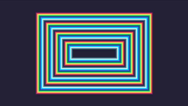
To demo our rectangle drawing, we will draw a series of rectangles inside each other using every colour in the palette:
There are two different rendering modules to support different FPGAs. The 320x180 version has sixteen colours, while the 160x90 version has four; see Lines and Triangles for an explanation.
The 16-colour 320x180 version is shown below:
module render_rects #(
    parameter CORDW=16,  // signed coordinate width (bits)
    parameter CIDXW=4,   // colour index width (bits)
    parameter SCALE=1    // drawing scale: 1=320x180, 2=640x360, 4=1280x720
    ) (
    input  wire logic clk,    // clock
    input  wire logic rst,    // reset
    input  wire logic oe,     // output enable
    input  wire logic start,  // start drawing
    output      logic signed [CORDW-1:0] x,  // horizontal draw position
    output      logic signed [CORDW-1:0] y,  // vertical draw position
    output      logic [CIDXW-1:0] cidx,  // pixel colour
    output      logic drawing,  // actively drawing
    output      logic done      // drawing is complete (high for one tick)
    );

    localparam SHAPE_CNT=64;  // number of shapes to draw
    logic [$clog2(SHAPE_CNT):0] shape_id;  // shape identifier
    logic signed [CORDW-1:0] vx0, vy0, vx1, vy1;  // shape coords
    logic draw_start, draw_done;  // drawing signals

    // draw state machine
    enum {IDLE, INIT, DRAW, DONE} state;
    always_ff @(posedge clk) begin
        case (state)
            INIT: begin  // register coordinates and colour
                draw_start <= 1;
                state <= DRAW;
                vx0 <=  60 + shape_id;
                vy0 <=  20 + shape_id;
                vx1 <= 260 - shape_id;
                vy1 <= 160 - shape_id;
                cidx <= shape_id[3:0];  // use lowest four bits for colour
            end
            DRAW: begin
                draw_start <= 0;
                if (draw_done) begin
                    if (shape_id == SHAPE_CNT-1) begin
                        state <= DONE;
                    end else begin
                        shape_id <= shape_id + 1;
                        state <= INIT;
                    end
                end
            end
            DONE: state <= DONE;
            default: if (start) state <= INIT;  // IDLE
        endcase
        if (rst) state <= IDLE;
    end

    draw_rectangle #(.CORDW(CORDW)) draw_rectangle_inst (
        .clk,
        .rst,
        .start(draw_start),
        .oe,
        .x0(vx0 * SCALE),
        .y0(vy0 * SCALE),
        .x1(vx1 * SCALE),
        .y1(vy1 * SCALE),
        .x,
        .y,
        .drawing,
        .busy(),
        .done(draw_done)
    );

    always_comb done = (state == DONE);
endmodule
We then dust off our top_demo module from last time with one minor change (see below):
- iCEBreaker (iCE40): ice40/top_demo.sv
- Arty (XC7): xc7/top_demo.sv
- Nexys Video (XC7): xc7-dvi/top_demo.sv
- Verilator Sim: sim/top_demo.sv
Building the Designs
In the 2D Shapes section of the git repo, you’ll find the design files, a makefile for iCEBreaker and Verilator, and a Vivado project for Xilinx-based boards. There are also build instructions for boards and simulations.
You should see something like this (the iCEBreaker version has only four colours):
Speed Up
Now we’re drawing many pixels, we’ve increased drawing speed from one to 480 pixels per frame by drawing every 640x480 screen line using line_sys:
    // reduce drawing speed to make process visible
    localparam FRAME_WAIT = 200;  // wait this many frames to start drawing
    logic [$clog2(FRAME_WAIT)-1:0] cnt_frame_wait;
    logic draw_oe;  // draw requested
    always_ff @(posedge clk_sys) begin
        draw_oe <= 0;  // comment out to draw at full speed
        if (cnt_frame_wait != FRAME_WAIT-1) begin  // wait for initial frames
            if (frame_sys) cnt_frame_wait <= cnt_frame_wait + 1;
        end else if (line_sys) draw_oe <= 1;  // every screen line
    end
Colouring In
A rectangle is the simplest shape to fill: we draw a series of horizontal lines of the same length. We could use our existing draw_line module to do this, but a simpler approach has advantages. By restricting line drawing to one dimension and left-to-right, we can take advantage of sequential memory access, vital for dynamic memory (SDRAM, DDR, PSRAM) performance.
- Filled rectangle rasterization: draw_rectangle_fill.sv
- 1D line drawing: draw_line_1d.sv.
- Test bench for 1D line (Vivado): xc7/draw_line_1d_tb.sv.
And we have new render modules to demo filled rectangles:
Replace replace render_* with render_rect_fill in your top module and rebuild.

Filled Triangle
A filled triangle requires more thought than a rectangle. There are several different approaches; for example, barycentric coordinates can render many pixels in parallel on a modern GPU. We’ll stick with Bresenham’s algorithm, as it’s light on FPGA resources and can still draw over a million small triangles per second on Arty at 125 MHz (a sample 36-pixel triangle requires 97 clock cycles).
We use Bresenham to determine the triangle edges and then join them with a horizontal line. First, we sort the vertices, so we always draw down the screen, and then we split the triangle into two flat triangles.
Filled triangle rasterization - draw_triangle_fill.sv:
module draw_triangle_fill #(parameter CORDW=16) (  // signed coordinate width
    input  wire logic clk,             // clock
    input  wire logic rst,             // reset
    input  wire logic start,           // start triangle drawing
    input  wire logic oe,              // output enable
    input  wire logic signed [CORDW-1:0] x0, y0,  // vertex 0
    input  wire logic signed [CORDW-1:0] x1, y1,  // vertex 1
    input  wire logic signed [CORDW-1:0] x2, y2,  // vertex 2
    output      logic signed [CORDW-1:0] x,  y,   // drawing position
    output      logic drawing,         // actively drawing
    output      logic busy,            // drawing request in progress
    output      logic done             // drawing is complete (high for one tick)
    );

    // sorted input vertices
    logic signed [CORDW-1:0] x0s, y0s, x1s, y1s, x2s, y2s;

    // line coordinates
    logic signed [CORDW-1:0] x0a, y0a, x1a, y1a, xa, ya;
    logic signed [CORDW-1:0] x0b, y0b, x1b, y1b, xb, yb;
    logic signed [CORDW-1:0] x0h, x1h, xh;

    // previous y-value for edges
    logic signed [CORDW-1:0] prev_y;

    // previous x-values for horizontal line
    logic signed [CORDW-1:0] prev_xa;
    logic signed [CORDW-1:0] prev_xb;

    // line control signals
    logic oe_a, oe_b, oe_h;
    logic drawing_h;
    logic busy_a, busy_b, busy_h;
    logic b_edge;  // which B edge are we drawing?

    // pipeline completion signals to match coordinates
    logic busy_p1, done_p1;

    // draw state machine
    enum {IDLE, SORT_0, SORT_1, SORT_2, INIT_A, INIT_B0, INIT_B1, INIT_H,
            START_A, START_B, START_H, EDGE, H_LINE, DONE} state;
    always_ff @(posedge clk) begin
        case (state)
            SORT_0: begin
                state <= SORT_1;
                if (y0 > y2) begin
                    x0s <= x2;
                    y0s <= y2;
                    x2s <= x0;
                    y2s <= y0;
                end else begin
                    x0s <= x0;
                    y0s <= y0;
                    x2s <= x2;
                    y2s <= y2;
                end
            end
            SORT_1: begin
                state <= SORT_2;
                if (y0s > y1) begin
                    x0s <= x1;
                    y0s <= y1;
                    x1s <= x0s;
                    y1s <= y0s;
                end else begin
                    x1s <= x1;
                    y1s <= y1;
                end
            end
            SORT_2: begin
                state <= INIT_A;
                if (y1s > y2s) begin
                    x1s <= x2s;
                    y1s <= y2s;
                    x2s <= x1s;
                    y2s <= y1s;
                end
            end
            INIT_A: begin
                state <= INIT_B0;
                x0a <= x0s;
                y0a <= y0s;
                x1a <= x2s;
                y1a <= y2s;
                prev_xa <= x0s;
                prev_xb <= x0s;
            end
            INIT_B0: begin
                state <= START_A;
                b_edge <= 0;
                x0b <= x0s;
                y0b <= y0s;
                x1b <= x1s;
                y1b <= y1s;
                prev_y <= y0s;
            end
            INIT_B1: begin
                state <= START_B;  // we don't need to start A again
                b_edge <= 1;
                x0b <= x1s;
                y0b <= y1s;
                x1b <= x2s;
                y1b <= y2s;
                prev_y <= y1s;
            end
            START_A: state <= START_B;
            START_B: state <= EDGE;
            EDGE: begin
                if ((ya != prev_y || !busy_a) && (yb != prev_y || !busy_b)) begin
                    state <= START_H;
                    x0h <= (prev_xa > prev_xb) ? prev_xb : prev_xa;  // always draw...
                    x1h <= (prev_xa > prev_xb) ? prev_xa : prev_xb;  // left to right
                end
            end
            START_H: state <= H_LINE;
            H_LINE: begin
                if (!busy_h) begin
                    prev_y <= yb;  // safe to update previous values once h-line done
                    prev_xa <= xa;
                    prev_xb <= xb;
                    if (!busy_b) begin
                        state <= (busy_a && b_edge == 0) ? INIT_B1 : DONE;
                    end else state <= EDGE;
                end
            end
            DONE: begin
                state <= IDLE;
                done_p1 <= 1;
                busy_p1 <= 0;
            end
            default: begin  // IDLE
                if (start) begin
                    state <= SORT_0;
                    busy_p1 <= 1;
                end
                done_p1 <= 0;
            end
        endcase

        if (rst) begin
            state <= IDLE;
            busy_p1 <= 0;
            done_p1 <= 0;
            b_edge <= 0;
        end
    end

    always_comb begin
        oe_a = (state == EDGE && ya == prev_y);
        oe_b = (state == EDGE && yb == prev_y);
        oe_h = oe;
    end

    // register output
    always_ff @(posedge clk) begin
        x <= xh;
        y <= prev_y;
        drawing <= drawing_h;
        busy <= busy_p1;
        done <= done_p1;
    end

    draw_line #(.CORDW(CORDW)) draw_edge_a (
        .clk,
        .rst,
        .start(state == START_A),
        .oe(oe_a),
        .x0(x0a),
        .y0(y0a),
        .x1(x1a),
        .y1(y1a),
        .x(xa),
        .y(ya),
        .drawing(),
        .busy(busy_a),
        .done()
    );

    draw_line #(.CORDW(CORDW)) draw_edge_b (
        .clk,
        .rst,
        .start(state == START_B),
        .oe(oe_b),
        .x0(x0b),
        .y0(y0b),
        .x1(x1b),
        .y1(y1b),
        .x(xb),
        .y(yb),
        .drawing(),
        .busy(busy_b),
        .done()
    );

    draw_line_1d #(.CORDW(CORDW)) draw_h_line (
        .clk,
        .rst,
        .start(state == START_H),
        .oe(oe_h),
        .x0(x0h),
        .x1(x1h),
        .x(xh),
        .drawing(drawing_h),
        .busy(busy_h),
        .done()
    );
endmodule
I’ve created two demo modules for filled triangles. The first draw three triangles:
Replace replace render_* with render_triangles_fill in your top module and rebuild.

The second demo creates a filled cube with six triangles:
Replace replace render_* with render_cube_fill in your top module and rebuild.

Shared Responsibility
When two triangles share an edge, we must decide which triangle draws that edge. The standard approach is to draw the top and left edges, but we won’t don’t handle this just yet.
Circles
Circles are surprisingly straightforward to draw. I’ve based my designs on the algorithm from The Beauty of Bresenham’s Algorithm, which requires neither multiplication nor division.
Algorithm details to follow.
- Circle rasterization - draw_circle.sv
- Filled circle rasterization - draw_circle_fill.sv
- Test bench for circle (Vivado): xc7/draw_circle_tb.sv.
Replace replace render_* with render_circles in your top module and rebuild.

Replace replace render_* with render_circles_fill in your top module and rebuild.
In the simulation, you should see this:

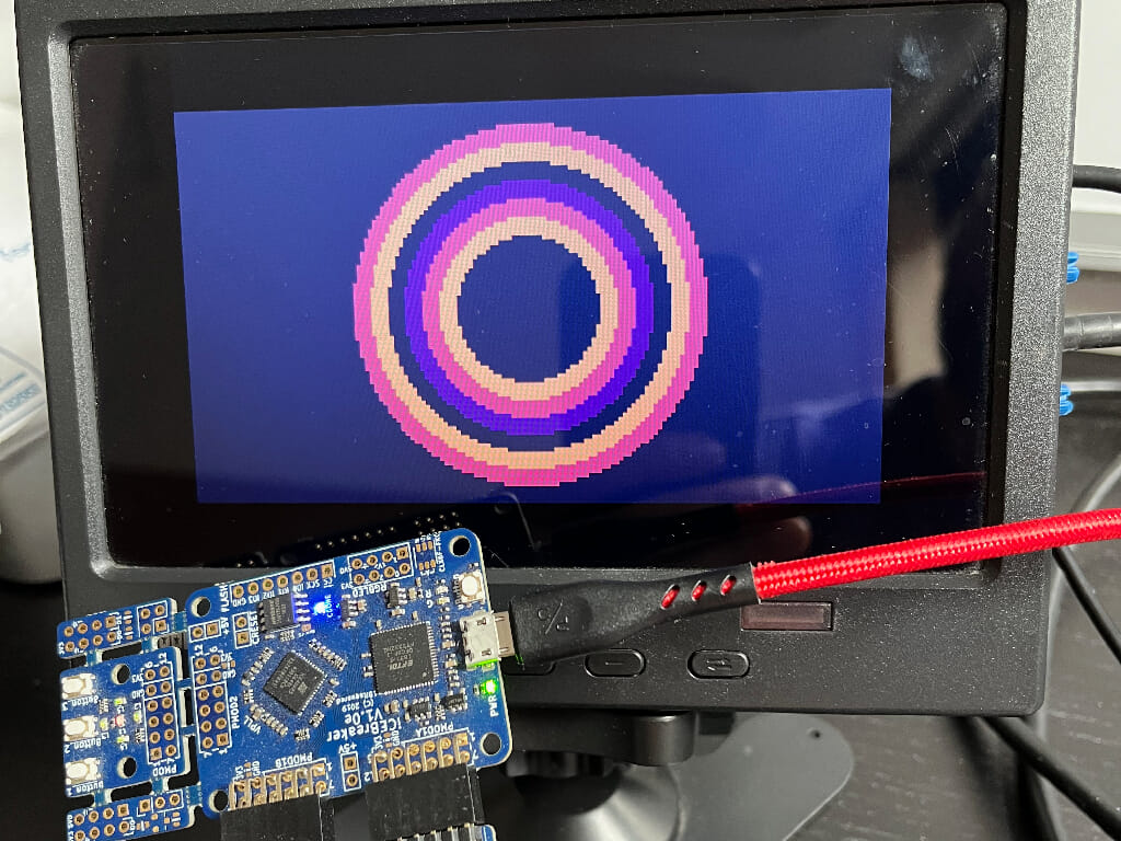
On the iCEBreaker, you should see something like this (four colour):
Explore
I hope you enjoyed this instalment of Exploring FPGA Graphics, but nothing beats creating your own designs. Here are a few suggestions to get you started:
- Draw a filled hexagon using filled triangles
- Draw a pair of eyes using only circles
- Check out the Castle Drawing Demo, which combines multiple shapes
- Recreate the Pink Floyd album cover for The Dark Side of the Moon
What’s Next?
Next time in FPGA Graphics, we’ll be moving around with Animated Shapes.