Life on Screen
In this FPGA demo we’ll experiment with Game of Life, a cellular automaton created by prolific mathematician John Conway in 1970.
NB. This demo uses an old framebuffer design. For new projects, I recommend following Framebuffers.

Requirements
For this demo you need an FPGA board with video output. I’ll be working with the Digilent A7 Arty, but it should be easy to adapt this design to other boards. It helps to be comfortable with programming your FPGA board and reasonably familiar with Verilog.
If you’ve not played with FPGA graphics before, check out Beginning FPGA Graphics.
Conway’s Life
He is Archimedes, Mick Jagger, Salvador Dalí, and Richard Feynman, all rolled into one.
The Guardian, John Horton Conway: the world’s most charismatic mathematician (2015)
John Conway was a remarkable mathematician, active in many fields, who sadly died in 2020. Conway is best known to the public for recreational mathematics with Martin Gardner in Scientific American. I remember playing Sprouts at school and trying to impress people by calculating the day of the week with the Doomsday rule. For now, I’ll be limiting myself to Game of Life, but I highly recommend learning more of Conway: The world’s most charismatic mathematician is an excellent place to start.
Game of Life first appeared in the Mathematical Games column in the October 1970 issue of Scientific American. Anyone can access the article at ibiblio.org, or you can see a scan of the original at JSTOR (requires login via academic institution or library).
The Rules of Life
The universe of the Game of Life is an infinite, two-dimensional, grid of cells. A cell is one of two states: dead or alive. Every cell interacts with its eight neighbours (those to the left, right, top, bottom, and the four diagonals).
The following rules determine the fate of a cell in the next generation:
- Survival: Every cell with two or three neighbours survives.
- Deaths:
a. Every cell with four or more neighbours dies from overpopulation.
b. Every cell with zero or one neighbours dies from isolation. - Births: Every empty cell with exactly three neighbours comes to life.
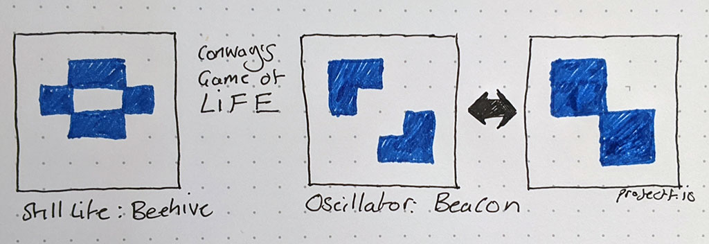
To understand this, it helps to see some practical examples. Common patterns within the Life universe have been given names. The diagram below shows two patterns: “Beehive” and “Beacon”.

Every live cell in the Beehive pattern has two or three neighbours: so, no cells die. No dead cells in Beehive have three neighbours: so, no cells come to life. This pattern is categorised as a “still life”, because it doesn’t change from one generation to the next.
The Beacon pattern is a bit more interesting: it oscillates between two states. Two dead cells in the centre of the pattern have three neighbours, so come to life. However, they then have four neighbours, so die the next generation due to overcrowding: this pattern repeats endlessly.
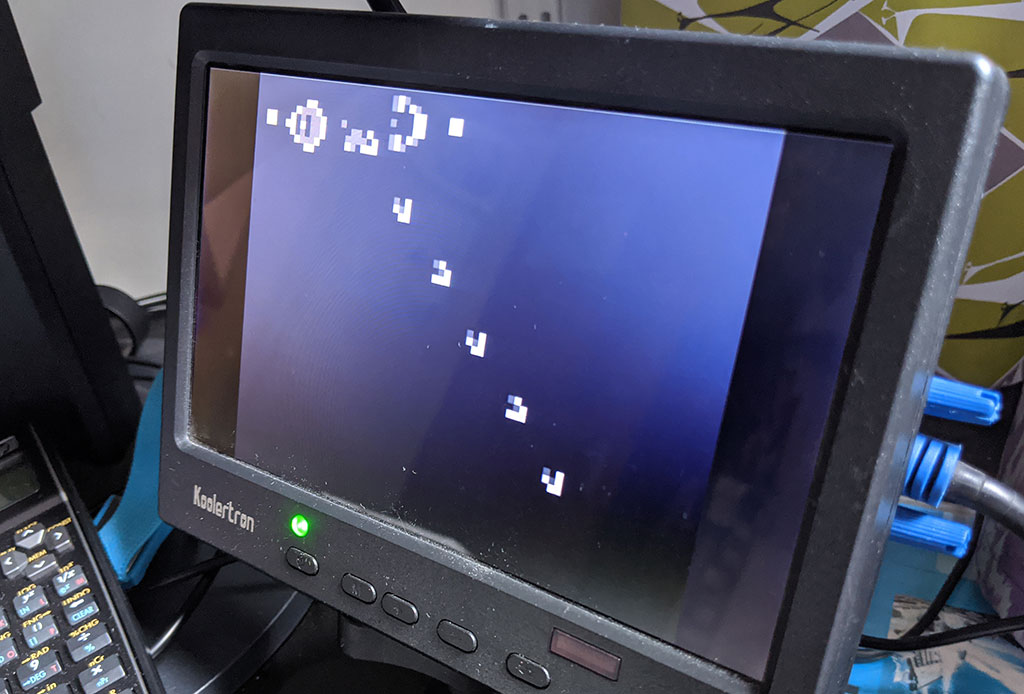
However, things start to get really interesting with slightly more complex patters. The following photo shows the Gosper glider gun running on the Arty board. The gun repeatedly generates small patterns called gliders that step across the world.

It’s even possible to construct logic gates using gliders, and ultimately a universal Turing machine. For this little demo, we’re not going to dig further into the esoteric possibilities of Conway’s Life, but check out Wikipedia’s article on Conway’s Game of Life.
A Hard Life
Now we have a basic understanding of Life, we’re going to create a hardware implementation.
Let’s start by rearranging the rules to simplify the design:
- If a cell is alive
a. if it has 2 or 3 neighbours, it’s alive next generation
b. otherwise, it’s dead next generation - If a cell is dead
a. if it has 3 neighbours, it’s alive next generation
b. otherwise, it’s dead next generation
We need a two-dimensional array to hold our world. Our memory array obviously can’t be infinite, so we need a way to handle the edges.
- Surround the world with a border of dead cells
- Wrap the world around at left and right, and at top and bottom
Both approaches have their advantages and disadvantages, but I’ll be using option 1 for this demo.
Since a cell’s state depends on all those around it, we can’t calculate the new state of each cell with one array. Instead, we have two array (or buffers): one contains the current generation; we use it to calculate the next generation in the second buffer. Every generation, we swap buffers and repeat the generation process.
Life Module
The rules of life are expressed in [life.sv]:
module life #(
    parameter CORDW=16,   // signed coordinate width
    parameter WIDTH=6,    // world width in cells
    parameter HEIGHT=6,   // world height in cells
    parameter F_INIT=""   // initial world state
    ) (
    input  wire logic clk,      // clock
    input  wire logic rst,      // reset
    input  wire logic start,    // start generation
    output      logic ready,    // cell state ready to be read
    output      logic alive,    // is the cell alive? (when ready)
    output      logic changed,  // cell's state changed (when ready)
    output      logic signed [CORDW-1:0] x,  // horizontal cell position
    output      logic signed [CORDW-1:0] y,  // vertical cell position
    output      logic running,  // life is running
    output      logic done      // generation complete (high for one tick)
    );

    // world buffer selection
    logic next_gen;  // where to write the next generation
    always_ff @(posedge clk) begin
        if (start) next_gen <= ~next_gen;  // swap every generation
        if (rst) next_gen <= 0;
    end

    // world in BRAM
    localparam DATAW = 1;  // cells are either dead or alive
    localparam WORLD_WIDTH  = WIDTH  + 2;  // wider to handle boundary
    localparam WORLD_HEIGHT = HEIGHT + 2;  // taller to handle boundary
    localparam WORLD_CELLS = WORLD_WIDTH * WORLD_HEIGHT;
    localparam DEPTH = 2 * WORLD_CELLS;
    localparam ADDRW = $clog2(DEPTH);

    logic we;
    logic [ADDRW-1:0] cell_id, addr_read;  // cell_id is basis of write address
    logic [DATAW-1:0] data_in, data_out;

    // add offset to read and write addresses to match buffer used
    logic [ADDRW-1:0] addr_read_offs, addr_write_offs;
    always_comb begin
        addr_read_offs = addr_read + ((next_gen) ? 0 : WORLD_CELLS);
        addr_write_offs = cell_id + ((next_gen) ? WORLD_CELLS : 0);
    end

    bram_sdp #(
        .WIDTH(DATAW),
        .DEPTH(DEPTH),
        .INIT_F(F_INIT)
    ) bram_inst (
        .clk_write(clk),
        .clk_read(clk),
        .we,
        .addr_write(addr_write_offs),
        .addr_read(addr_read_offs),
        .data_in,
        .data_out
    );

    // cell coordinates
    localparam GRID = 3;    // neighbours are a 3x3 grid
    localparam STEPS = 11;  // 9 reads and 2 cycles of latency
    logic [$clog2(WORLD_WIDTH)-1:0]  cell_x;  // active cell (horizontal)
    logic [$clog2(WORLD_HEIGHT)-1:0] cell_y;  // active cell (vertical)
    logic [$clog2(STEPS)-1:0] read_step;      // reading step
    logic inc_read;                           // perform incremental read
    logic [GRID-1:0] top_sr, mid_sr, bot_sr;  // shift reg for neighbours
    logic [$clog2(GRID*GRID)-1:0] neigh_cnt;  // count of neighbours

    // life generation state
    enum {IDLE, INIT, READ, NEIGH, UPDATE, NEW_CELL, NEW_LINE} state;
    always_ff @(posedge clk) begin
        // single-cycle flags: 0 by default
        ready <= 0;
        we <= 0;
        done <= 0;

        case(state)
            INIT: begin
                read_step <= 0;
                inc_read <= 0;
                top_sr <= 0;
                mid_sr <= 0;
                bot_sr <= 0;
                neigh_cnt <= 0;
                state <= READ;
                running <= 1;

                // first cell after padding
                cell_x <= 1;
                cell_y <= 1;
                cell_id <= WORLD_WIDTH + 1;
            end
            READ: begin  // 1 cycle to set address and 1 cycle BRAM read latency
                case (read_step)
                    4'd0: begin
                        addr_read <= cell_id - WORLD_WIDTH - 1;  // A
                    end
                    4'd1: begin
                        addr_read <= cell_id - 1;  // B
                    end
                    4'd2: begin
                        addr_read <= cell_id + WORLD_WIDTH - 1;  // C
                        if (!inc_read) top_sr <= {top_sr[1:0], data_out};  // A
                    end
                    4'd3: begin
                        addr_read <= cell_id - WORLD_WIDTH;  // D
                        if (!inc_read) mid_sr <= {mid_sr[1:0], data_out};  // B
                    end
                    4'd4: begin
                        addr_read <= cell_id;  // E
                        if (!inc_read) bot_sr <= {bot_sr[1:0], data_out};  // C
                    end
                    4'd5: begin
                        addr_read <= cell_id + WORLD_WIDTH;  // F
                        if (!inc_read) top_sr <= {top_sr[1:0], data_out};  // D
                    end
                    4'd6: begin
                        addr_read <= cell_id - WORLD_WIDTH + 1;  // G
                        if (!inc_read) mid_sr <= {mid_sr[1:0], data_out};  // E
                    end
                    4'd7: begin
                        addr_read <= cell_id + 1;  // H
                        if (!inc_read) bot_sr <= {bot_sr[1:0], data_out};  // F
                    end
                    4'd8: begin
                        addr_read <= cell_id + WORLD_WIDTH + 1;  // I
                        top_sr <= {top_sr[1:0], data_out};  // G
                    end
                    4'd9: begin
                        mid_sr <= {mid_sr[1:0], data_out};  // H
                    end
                    4'd10: begin
                        bot_sr <= {bot_sr[1:0], data_out};  // I
                    end
                    default: addr_read <= 0;
                endcase

                if (read_step == STEPS-1) state <= NEIGH;
                else read_step <= read_step + 1;
            end
            NEIGH: begin
                neigh_cnt <= top_sr[0] + top_sr[1] + top_sr[2] +
                             mid_sr[0]             + mid_sr[2] +
                             bot_sr[0] + bot_sr[1] + bot_sr[2];
                state <= UPDATE;
            end
            UPDATE: begin
                // update cell state
                we <= 1;     // write new cell state next cycle
                ready <= 1;  // ready for output next cycle
                x <= cell_x - 1;  // correct horizontal position for padding
                y <= cell_y - 1;  // correct vertical position for padding

                if (mid_sr[1]) begin // cell was alive this generation
                    if (neigh_cnt == 2 || neigh_cnt == 3) begin  // still alive
                        data_in <= 1;
                        alive <= 1;
                        changed <= 0;
                    end else begin  // now dead
                        data_in <= 0;
                        alive <= 0;
                        changed <= 1;
                    end
                end else begin  // was dead this generation
                    if (neigh_cnt == 3) begin  // now alive
                        data_in <= 1;
                        alive <= 1;
                        changed <= 1;
                    end else begin  // still dead
                        data_in <= 0;
                        alive <= 0;
                        changed <= 0;
                    end
                end

                // what next?
                if (cell_x == WORLD_WIDTH-2) begin  // final cell on line
                    if (cell_y == WORLD_HEIGHT-2) begin  // final line of cells
                        state <= IDLE;
                        running <= 0;
                        done <= 1;
                    end else state <= NEW_LINE;
                end else state <= NEW_CELL;
            end
            NEW_CELL: begin
                cell_x <= cell_x + 1;
                cell_id <= cell_id + 1;
                inc_read  <= 1;  // incremental read
                read_step <= 6;  // read new column of 3 cells (skip A-F)
                state <= READ;
            end
            NEW_LINE: begin
                cell_y <= cell_y + 1;
                cell_x <= 1;
                cell_id <= cell_id + 3;  // skip 2 cells of padding
                read_step <= 0;  // read all nine cells at start of line
                state <= READ;
            end
            default: state <= (start) ? INIT : IDLE;  // IDLE
        endcase
        if (rst) begin
            state <= IDLE;
            ready <= 0;
            alive <= 0;
            changed <= 0;
            x <= 0;
            y <= 0;
            running <= 0;
            done <= 0;
        end
    end
endmodule
To exercise this module I’ve created test bench for Vivado: [life_tb.sv].
Top Life
I’ve created a top module for the Arty board to run the life instance - [xc7/top_life.sv]:
module top_life (
    input  wire logic clk_100m,     // 100 MHz clock
    input  wire logic btn_rst_n,    // reset button (active low)
    output      logic vga_hsync,    // horizontal sync
    output      logic vga_vsync,    // vertical sync
    output      logic [3:0] vga_r,  // 4-bit VGA red
    output      logic [3:0] vga_g,  // 4-bit VGA green
    output      logic [3:0] vga_b   // 4-bit VGA blue
    );

    localparam GEN_FRAMES = 15;  // each generation lasts this many frames
    localparam SEED_FILE = "simple_64x48.mem";  // world seed
    // localparam SEED_FILE = "gosper_gun_64x48.mem";  // world seed

    // generate pixel clock
    logic clk_pix;
    logic clk_pix_locked;
    logic rst_pix;
    clock_480p clock_pix_inst (
       .clk_100m,
       .rst(!btn_rst_n),  // reset button is active low
       .clk_pix,
       .clk_pix_5x(),  // not used for VGA output
       .clk_pix_locked
    );
    always_ff @(posedge clk_pix) rst_pix <= !clk_pix_locked;  // wait for clock lock

    // display sync signals and coordinates
    localparam CORDW = 16;
    logic hsync, vsync;
    logic de, frame, line;
    display_480p #(.CORDW(CORDW)) display_inst (
        .clk_pix,
        .rst_pix,
        .sx(),
        .sy(),
        .hsync,
        .vsync,
        .de,
        .frame,
        .line
    );

    logic frame_sys;  // start of new frame in system clock domain
    xd xd_frame (.clk_src(clk_pix), .clk_dst(clk_100m),
        .flag_src(frame), .flag_dst(frame_sys));

    // life signals
    logic life_start, life_alive, life_changed;

    // start life generation in blanking every GEN_FRAMES
    logic [$clog2(GEN_FRAMES)-1:0] cnt_frames;
    always_ff @(posedge clk_100m) begin
        life_start <= 0;
        if (frame_sys) begin
            if (cnt_frames == GEN_FRAMES-1) begin
                life_start <= 1;
                cnt_frames <= 0;
            end else cnt_frames <= cnt_frames + 1;
        end
    end

    // framebuffer (FB)
    localparam FB_WIDTH   = 64;
    localparam FB_HEIGHT  = 48;
    localparam FB_CIDXW   = 2;
    localparam FB_CHANW   = 4;
    localparam FB_SCALE   = 10;
    localparam FB_IMAGE   = "";
    localparam FB_PALETTE = "life_palette.mem";

    logic fb_we;
    logic signed [CORDW-1:0] fbx, fby;  // framebuffer coordinates
    logic [FB_CIDXW-1:0] fb_cidx;
    logic fb_busy;  // when framebuffer is busy it cannot accept writes
    logic [FB_CHANW-1:0] fb_red, fb_green, fb_blue;  // colours for display

    framebuffer_bram #(
        .WIDTH(FB_WIDTH),
        .HEIGHT(FB_HEIGHT),
        .CIDXW(FB_CIDXW),
        .CHANW(FB_CHANW),
        .SCALE(FB_SCALE),
        .F_IMAGE(FB_IMAGE),
        .F_PALETTE(FB_PALETTE)
    ) fb_inst (
        .clk_sys(clk_100m),
        .clk_pix,
        .rst_sys(1'b0),
        .rst_pix(1'b0),
        .de,
        .frame,
        .line,
        .we(fb_we),
        .x(fbx),
        .y(fby),
        .cidx(fb_cidx),
        .busy(fb_busy),
        .clip(),
        .red(fb_red),
        .green(fb_green),
        .blue(fb_blue)
    );

    // select colour based on cell state
    always_comb fb_cidx = {1'b0, life_alive};

    life #(
        .CORDW(CORDW),
        .WIDTH(FB_WIDTH),
        .HEIGHT(FB_HEIGHT),
        .F_INIT(SEED_FILE)
    ) life_inst (
        .clk(clk_100m),          // clock
        .rst(1'b0),              // reset
        .start(life_start),      // start generation
        .ready(fb_we),           // cell state ready to be read
        .alive(life_alive),      // is the cell alive? (when ready)
        .changed(life_changed),  // cell's state changed (when ready)
        .x(fbx),                 // horizontal cell position
        .y(fby),                 // vertical cell position
        .running(),              // life is running
        .done()                  // generation complete (high for one tick)
    );

    // reading from FB takes one cycle: delay display signals to match
    logic hsync_p1, vsync_p1;
    always_ff @(posedge clk_pix) begin
        hsync_p1 <= hsync;
        vsync_p1 <= vsync;
    end

    // VGA output
    always_ff @(posedge clk_pix) begin
        vga_hsync <= hsync_p1;
        vga_vsync <= vsync_p1;
        vga_r <= fb_red;
        vga_g <= fb_green;
        vga_b <= fb_blue;
    end
endmodule
I’ve used a 64x48 world, which is a tenth of the 640x480 screen dimensions. With the padding of dead cells, each world array has 66 x 50 = 3,300 cells, which comfortably fits into 4Kb.
Building the Demo
In the Life on Screen section of the git repo, you’ll find the design files and build instructions.
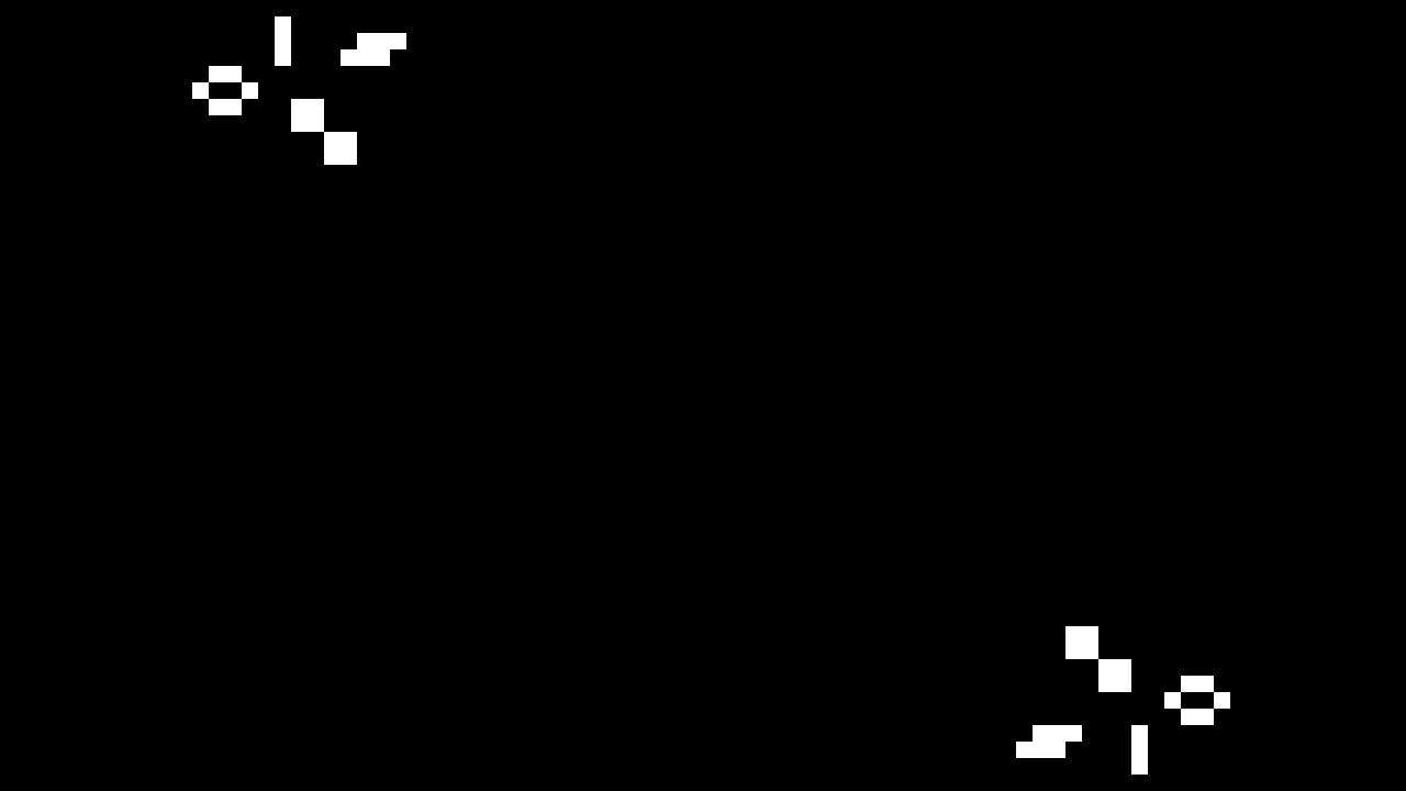
Once you’ve programmed your board, you should see a simple test pattern of oscillators and a still life (capture from FPGA board shown below).

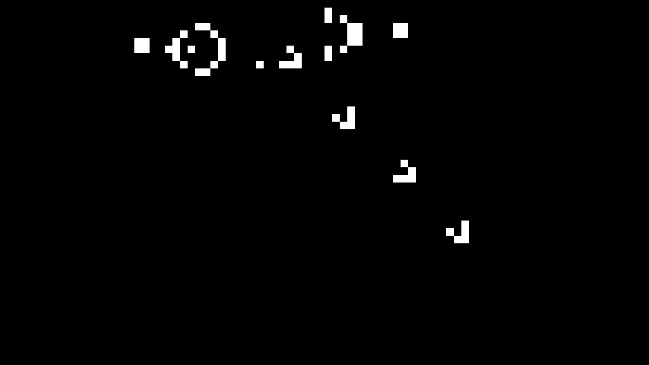
If that works, try the Gosper glider gun by changing the seed file in top_life.sv:
localparam SEED_FILE = "gosper_gun_64x48.mem"; // world seed
The Gosper pattern repeatedly generates small gliders that move down the screen. Our gliders doesn’t continue indefinitely because our world is currently surrounded by dead cells, which kill the gliders when they collide with it.
You can also change how fast Life runs by adjusting GEN_FRAMES:
localparam GEN_FRAMES = 4; // each generation lasts this many frames
At 60 frames per second, a value of ‘4’ results in 15 generations per second.

What’s Next?
Check out my FPGA graphics tutorials.
Peter Hizalev has written a version of Game of Life in Chisel that simulates every cell simultaneously!