Isle Input Output
Published 20 Mar 2026 (DRAFT)
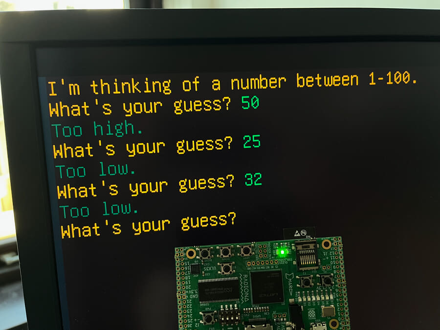
In chapter 6 of Building Isle, we consider how information gets into the computer, and we start developing a RISC-V software library. Combining keyboard input, text mode, and random number generation, we introduce our first game.
If you're new to the project, read Isle FPGA Computer for an introduction. See Isle Index for more pages.
Input
Without any input, we can't interact with our computer; it can't respond to us. Want to edit text, play a game, or paint? We need input, and it's about time we added it to Isle. Another reason to add input is debugging. Even simple software is horrible to debug in a waveform monitor. With keyboard input, we can implement a debug monitor to make software development easier, and we'll cover this in the next chapter.
Any input raises important questions in computer design. Input can occur at any time; if a user presses a key, we must handle it immediately, or the data will be lost. Interrupts are a common solution, but they introduce extra complexity we do not want to address right now. In this chapter, we will design a simple UART and FIFO combination to handle keyboard input.
A UART (Universal Asynchronous Receiver-Transmitter) is often the first hardware added to a new system. If we look behind its imposing name, it's a simple serial interface with a transmit wire and a receive wire. Your main computer probably doesn't have a serial port, so it's common for dev boards to include a USB-to-serial IC (often from FTDI).
Let's start by building the chapter 6 design, then discuss the hardware and software.

Building
The hardware build process is the same as earlier chapters. Each dev board has its own top module:
- Lakritz: boards/lakritz/ch06/top_ch06.v (build instructions)
- Nexys Video: boards/nexys_video/ch06/top_ch06.v (build instructions)
- ULX3S: boards/ulx3s/ch06/top_ch06.v (build instructions)
- Verilator: boards/verilator/ch06/top_ch06.v (build instructions)
The Verilator simulation is easy to run on Linux/Mac/Windows, no dev board required.
To change the software loaded at design time, amend FILE_SOFT in your dev board's top_ch06.v. You need to reference the compiled .mem file from software/book/ch06 (discussed below).
Input Hardware
The chapter 6 input hardware has two components, a UART receiver and a FIFO.
UART Receiver
A conventional UART data frame (8N1) consists of:
- Idle - logic high (1)
- Start bit - logic low (0)
- Eight data bits
- Stop bit - logic high (1)
Isle uses 115200 baud (symbols per second). 115200 is widely supported and reasonably speedy, but without requiring Isle to provide large buffers or interrupts. 115200 baud is overkill for typing, but enables reasonable data transfer of ~11 KiB/second (1 MiB in 90 seconds), which will come in handy in the next chapter.
I've tried to make the Verilog UART receive module easy to understand and reasonably robust without going overboard; it's unlikely you're using this over a long, noisy serial cable. You can set the different parts of the UART data frame in the Verilog finite state machine.
Our system clock runs at 20 MHz. A UART transmitter doesn't include a clock signal, so our UART receiver needs to sample the UART data at a higher frequency than the 115200 baud. Isle uses 1.8432 MHz (16 x baud) as the sampling frequency. We detect the start bit by looking for a transition from logic high to low, then sample again in the middle of the bit (7 sampling cycles later) to ensure we really have a start bit and not a glitch on the wire.
How do we generate the sampling frequency of 1.8432 MHz? We could use a PLL to generate a sampling clock, but then we'd have clock-domain crossing issues, and PLLs are a precious resource. Instead, we use a counter-based clock divider in the UART receive module:
reg stb_16xbaud;
reg [UART_CNT_W-1:0] cnt_16xbaud;
always @(posedge clk) begin
    {stb_16xbaud, cnt_16xbaud} <= cnt_16xbaud + UART_CNT_INC;
The clock divider is controlled by two parameters:
parameter UART_CNT_INC=6036,  // 16 x baud counter increment
parameter UART_CNT_W=16, // 16 x baud counter width (bits)216 / 6036 = 10.876
20 MHz / 10.876 = 1.839 MHz
Our chosen dividers provide a sampling frequency 99.7% of target, which is more than precise enough for a UART, especially as we synchronise with the start bit every data frame.
The UART receiver module hardware/io/uart_rx.v (doc):
module uart_rx #(
    parameter UART_CNT_INC=6036,  // 16 x baud counter increment
    parameter UART_CNT_W=16,      // 16 x baud counter width (bits)
    parameter UART_DATAW=8        // UART data width (bits)
    ) (
    input  wire clk,        // clock
    input  wire rst,        // reset
    input  wire serial_in,  // serial data in
    output reg  [UART_DATAW-1:0] dout,  // data received
    output reg  rx_busy,    // busy receiving
    output reg  rx_done     // receive complete
    );

    // 16 x baud strobe generator
    reg stb_16xbaud;
    reg [UART_CNT_W-1:0] cnt_16xbaud;
    always @(posedge clk) begin
        {stb_16xbaud, cnt_16xbaud} <= cnt_16xbaud + UART_CNT_INC;

        if (rst) begin
            stb_16xbaud <= 0;
            cnt_16xbaud <= 0;
        end
    end

    // sampling params (only one sample in this implementation)
    localparam SAMPLES   = 16;  // samples per baud (must be power of 2)
    localparam SAMPLES_W = $clog2(SAMPLES);
    localparam [SAMPLES_W-1:0] SAMPLE_A    = SAMPLES/2 - 1;  // middle bit
    localparam [SAMPLES_W-1:0] SAMPLE_LAST = SAMPLES - 1;    // last sample

    // sync serial serial_in to combat metastability
    reg rx_0, rx;
    always @(posedge clk) begin
        rx_0 <= serial_in;
        rx <= rx_0;
        if (rst) begin  // default high as start is triggered by rx going low
            rx_0 <= 1;
            rx <= 1;
        end
    end

    // state machine
    localparam IDLE  = 0;
    localparam START = 1;
    localparam DATA  = 2;
    localparam STOP  = 3;
    localparam STATEW = 2;  // state width (bits) - must cover largest state machine param
    reg [STATEW-1:0] state, state_next;

    // data index
    localparam IDX_W = $clog2(UART_DATAW);
    reg [IDX_W-1:0] data_idx, data_idx_next;
    localparam [IDX_W-1:0] LAST_BIT = UART_DATAW - 1;

    // sample counter and data
    reg [SAMPLES_W-1:0] s_cnt, s_cnt_next;
    reg sample_a, sample_a_next;    // sample data
    reg [UART_DATAW-1:0] data_tmp;  // hold data output as we receive it
    reg bit_done, bit_done_next;    // bit ready to save
    reg rx_done_next;               // receive done next

    always @(posedge clk) begin
        state <= state_next;
        data_idx <= data_idx_next;
        s_cnt <= s_cnt_next;
        sample_a <= sample_a_next;
        bit_done <= bit_done_next;
        rx_done <= rx_done_next;

        if (rst) begin
            state <= IDLE;
            data_idx <= 0;
            s_cnt    <= 0;
            sample_a <= 0;
            rx_done  <= 0;
            bit_done <= 0;
        end
    end

    always @(*) begin
        state_next = state;  // remain in existing state by default
        data_idx_next = data_idx;
        s_cnt_next = s_cnt;
        sample_a_next = sample_a;
        bit_done_next = 0;  // default to 0 (high for one tick only)
        rx_done_next  = 0;

        case(state)
            IDLE: begin  // rx going low signals start
                if (rx == 0) begin
                    state_next = START;
                    s_cnt_next = 0;
                end
            end
            START: begin
                if (stb_16xbaud) begin
                    if (s_cnt == SAMPLE_A && rx == 1) begin
                        state_next = IDLE;  // abort if rx doesn't remain low
                    end else if (s_cnt == SAMPLE_LAST) begin
                        state_next = DATA;
                        data_idx_next = 0;
                        s_cnt_next = 0;
                    end else s_cnt_next = s_cnt + 1;
                end
            end
            DATA: begin
                if (stb_16xbaud) begin
                    if (s_cnt == SAMPLE_A) begin
                        sample_a_next = rx;
                        bit_done_next = 1;  // final sample
                        s_cnt_next = s_cnt + 1;
                    end else if (s_cnt == SAMPLE_LAST) begin
                        if (data_idx == LAST_BIT)
                            state_next = STOP;  // last data bit done?
                        else data_idx_next = data_idx + 1;
                        s_cnt_next = 0;
                    end else s_cnt_next = s_cnt + 1;
                end
            end
            STOP: begin
                if (stb_16xbaud) begin
                    if (s_cnt == SAMPLE_A) begin
                        sample_a_next = rx;
                        s_cnt_next = s_cnt + 1;
                    end else if (s_cnt == SAMPLE_LAST) begin
                        state_next = IDLE;
                        if (sample_a) rx_done_next = 1;  // only done if valid STOP
                    end else s_cnt_next = s_cnt + 1;
                end
            end
        endcase
    end

    always @(posedge clk) begin
        if (bit_done) data_tmp[data_idx] <= sample_a;
        if (rx_done_next) dout <= data_tmp;
        if (rst) begin
            dout <= 0;
            data_tmp <= 0;
        end
    end

    always @(*) rx_busy = (state != IDLE);
endmodule
I've also implemented a UART transmitter, hardware/io/uart_tx.v (doc), but we don't use it in this chapter because we have our own text mode for output.
FIFO
The FIFO (first in, first out) module is very simple: a memory and two pointers. The FIFO gives us a queue where we can write UART data as it arrives, and read it off at our leisure (well, as long as we do so before the FIFO gets full). Later, when we support interrupts, the FIFO reduces the number of times our CPU needs to be interrupted.
The synchronous (same clock for read and write) fifo module hardware/mem/fifo_sync.v (doc):
module fifo_sync #(
    parameter ADDRW=4,  // address width (bits)
    parameter DATAW=8   // data width (bits)
    ) (
    input  wire clk,               // clock
    input  wire rst,               // reset
    input  wire we,                // write enable
    input  wire re,                // read enable
    input  wire [DATAW-1:0] din,   // data in
    output reg  [DATAW-1:0] dout,  // data out
    output wire [ADDRW-1:0] len,   // length; number of items (occupancy)
    output wire empty,             // fifo empty
    output wire full               // fifo full
    );

    localparam DEPTH = 2**ADDRW;  // usable capacity is one less
    reg [DATAW-1:0] fifo_mem [0:DEPTH-1];

    reg [ADDRW-1:0] wptr, rptr;  // write and read pointers

    // status
    assign empty = (rptr == wptr);
    assign full  = ((wptr + 1) == rptr);
    assign len   = wptr - rptr;

    // write
    always @(posedge clk) begin
        if (rst) wptr <= 0;
        else if (we && !full) begin
            fifo_mem[wptr] <= din;
            wptr <= wptr + 1;
        end
    end

    // read
    always @(posedge clk) begin
        if (rst) rptr <= 0;
        else if (re && !empty) begin
            dout <= fifo_mem[rptr];
            rptr <= rptr + 1;
        end
    end
endmodule
Verilator
We obviously need to support keyboard input in our simulation, but routing signals from serial ports into LibSDL sounded like a rabbit hole I could do without. Instead, we encode key presses from LibSDL into UART serial data that the Verilog UART receiver can decode. Simulation input follows the same path as physical hardware, so we don't need any special hardware logic for it. My approach was to port the Verilog UART TX design from Verilog to C++, so it's no doubt far from the most efficient or idiomatic C++ (boards/verilator/sdl_sim.h).
class UartTx {
    enum State { IDLE, START, DATA, STOP };

    const uint32_t CNT_INC;    // counter increment
    const uint32_t CNT_BITS;   // width of counter
    const uint32_t CNT_MASK;   // mask data for strobe carry bit detection
    const uint8_t  DATAW = 8;  // only supports byte data width

    State state = IDLE;
    uint32_t cnt = 0;
    uint8_t data_reg = 0;
    uint8_t data_idx = 0;
    bool start_flag = false;

    std::queue<uint8_t> fifo_;  // safely queue up multiple bytes

public:
    uint8_t serial_out = 1;  // connect to Verilog serial input

    explicit UartTx(const UartConf& cfg = {})
        : CNT_INC(cfg.cnt_inc),
          CNT_BITS(cfg.cnt_w + 4),  // Verilog cnt_baud: [UART_CNT_W+3:0] = cnt_w+4 bits
          CNT_MASK((1U << (cfg.cnt_w  + 4)) - 1) {}

    void send(uint8_t byte) { fifo_.push(byte); }

    void send_str(const char *s) {
        while (*s) fifo_.push(static_cast<uint8_t>(*s++));
    }

    void tick () {
        // baud strobe
        uint32_t cnt_new = cnt + CNT_INC;  // increment counter
        bool stb = (cnt_new >> CNT_BITS) & 1;  // strobe if counter overflows
        cnt = cnt_new & CNT_MASK;  // mask counter to handle overflow

        // load data and set start flag when IDLE
        if (state == IDLE && !start_flag && !fifo_.empty()) {
            data_reg = fifo_.front();
            fifo_.pop();
            start_flag = true;
        }

        // output depends on the state
        switch (state) {
            case START: serial_out = 0; break;
            case DATA:  serial_out = (data_reg >> data_idx) & 1; break;
            default:    serial_out = 1; break;  // IDLE or STOP
        }

        // update state machine
        if (stb) {
            switch(state) {
                case IDLE:
                    if (start_flag) state = START;
                    break;
                case START:
                    state = DATA;
                    data_idx = 0;
                    start_flag = false;
                    break;
                case DATA:
                    if (data_idx == DATAW-1) {
                        state = STOP;
                    } else data_idx++;
                    break;
                case STOP:
                    state = IDLE;
                    break;
            }
        }
    }
};
Random
When writing the software for these early versions of Isle, I naturally turn to simple examples from simple computers. And it struck me that much of the life in these systems comes from randomness and trigonometry. I'm not ready to support trig yet, but I decided to introduce randomness, so we can start creating interesting things.

And it helps that I've already got a great way to create pseudo-random numbers in hardware: a linear-feedback shift register (LFSR). An LFSR can create a pseudorandom number sequence in which every number appears just once. For example, an 8-bit LSFR can generate all the numbers from 1 to 255 in a repeatable sequence that appears random.
The logic for an LFSR can be written in a single line of Verilog; for example, an 8-bit LFSR:
sreg <= {1'b0, sreg[7:1]} ^ (sreg[0] ? 8'b10111000 : 8'b0);The "magic" value 8'b10111000 is known as the "taps" and controls, which bits of the number are XOR'd. Isle uses a 32-bit LFSR; every clock cycle, a new 32-bit value is generated.
I've created a software function, rand_pseudo, which returns a random integer between n and m. It's part of the system library file, discussed below.
Chapter 6 Module
Before we get to the "root" chapter 6 module, I want to briefly mention devices. Devices provide a standard way for the CPU to access our hardware using memory-mapped I/O. Chapter 6 includes three devices:
- hardware/devs/gfx_dev.v - graphics hardware registers
- hardware/devs/sys_dev.v - lfsr and timer
- hardware/devs/uart_dev.v - uart receiver and fifo
The devices are mostly a wrapper around our existing hardware, providing hardware registers that the CPU can use to interact with the hardware.
Using these devices, we can create our root chapter 6 module: hardware/book/ch06/ch06.v.
Software
For chapter 6, we have four new examples and the start of a software library. See Chapter 6 Software for more details on the software.
Chapter 6 software examples (software/book/ch06):
- echo.s - echos back a line of UTF-8 text
- framecount.s - decimal frame counter
- guess.s - number guessing game
- resolution.s - view text mode and display resolutions
Compiling Software
The software examples are available pre-compiled in the Isle repo. If you'd like to compile them yourself or write your own, read the Software Build Guide.
Software Library
We have a simple text mode, but it's tedious to write directly to text mode memory. We want some nice functions to handle things such as cursor positioning, address calculation, and newlines, and that's an important focus for the software library in this chapter. We also introduce functions that can convert numbers to and from strings, and software to support our new input and random hardware. I'll write more about the library soon.
Chapter 6 software library (software/book/ch06/lib):
- gfx.s - only frame wait for now (handy for animation)
- io.s - read a byte from UART, read a line of text with editing
- string.s - number to/from string and UTF-8 functions
- sys.s - timer and pseudorandom numbers
- textmode.s - many functions to make text mode pleasant to use
Each function has a brief description in the source code. I'll add reference docs when we move to a common (rather than chapter specific) library, which should happen in a few chapters time.
There are also assembler include files (software/book/ch06/include) that define constants, such as hardware addresses.
RISC-V M Extension
Chapter 6 takes advantage of RISC-V M extension support in our CPU to multiply and divide. This is very useful for converting numbers to strings, amongst other things. See RISC-V Assembler: Multiply Divide for more details on these instructions.
Debug Monitor
With input and a basic software library up and running, next time we'll be building a debug monitor in the style of Wozmon, so we can examine and update memory, including hardware registers.
Next step: Chapter 7 - Debug Mon (under development), Chapter 6 Software, or Isle Index
Further Reading
- RISC-V Assembler Guide by Will Green