Isle Graphics Devices
Published 12 Sep 2026, Updated 15 Oct 2026 (DRAFT)
This post is a tale of two devices: Display and Earthrise. These graphic devices make the graphics CPU programmable for the first time. We can draw shapes, scroll the display, and set transparency.
If you're new to the project, read Isle FPGA Computer for an introduction. See Isle Index for more pages.
The Isle blog posts are drafts and will evolve as Isle evolves.
Devices
Isle devices provide an interface between our RISC-V CPU and the rest of the hardware, such as graphics, storage, and audio. Devices are mapped into the CPU's address space, so you can access them using normal memory operations, such as loads and stores.
Hardware is controlled through hardware registers. To avoid confusing Verilog registers with Isle hardware registers, I refer to Isle hardware registers as hwreg. For example, reading the DISP_DIMS_RO hwreg tells you the dimensions (resolution) of the Isle display, such as 1280x720.
The previous post introduced the first devices, and this post introduces two more:
- hardware/devs/dev_display.v (doc) - composite and display graphics (new)
- hardware/devs/dev_earthrise.v (doc) - Earthrise graphics engine (new)
- hardware/devs/dev_sys.v - lfsr and timer
- hardware/devs/dev_uart.v - uart receiver and fifo
Building
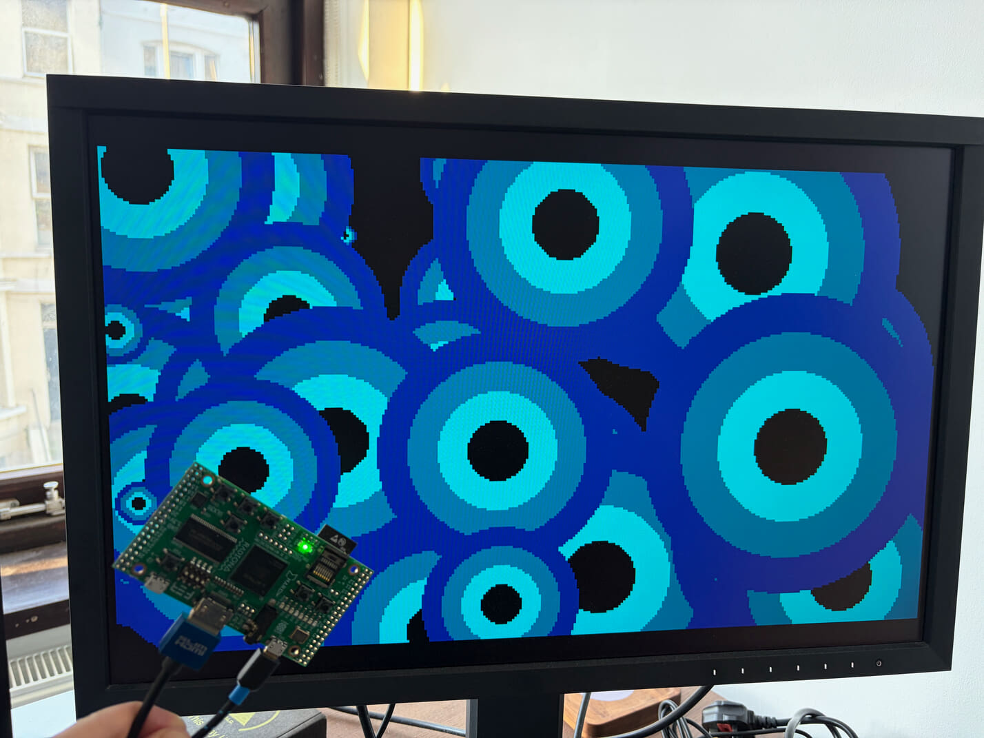
We'll look at the new device from a software perspective, but first I recommend you build the chapter 7 design, so you can see it running on your dev board or in simulation. You can see a photo of the design running, above.
The hardware build process is the same as earlier posts. Each dev board has its own top module:
- Lakritz: boards/lakritz/ch07/top_ch07.v (build instructions)
- Nexys Video: boards/nexys_video/ch07/top_ch07.v (build instructions)
- ULX3S: boards/ulx3s/ch07/top_ch07.v (build instructions)
- Verilator: boards/verilator/ch07/top_ch07.v (build instructions)
The Verilator simulation is easy to run on Linux/Mac/Windows; no dev board required.
To change the software loaded at design time, amend FILE_SOFT in your dev board's top_ch07.v. You need to reference the compiled .mem file from software/book/ch07 (discussed below).
Circles Software
The circle example uses Earthrise to draw random concentric circles onto a canvas; we then scroll that canvas using the display device. The hardware handles the low-level details, so the assembler is surprisingly short and simple. We have two loops, one to draw new circles and one to scroll the canvas. Both drawing and scrolling handle canvas wrapping, so no edges are visible. Have a glance through the asm, and I'll walk you through the different parts. I have a series covering RISC-V assembler if you want to learn or brush up your skills.
You can find the source in: software/book/ch07/circles.s.
.include "include/isle.inc"
.include "include/dev_display.inc"
.include "include/dev_earthrise.inc"
.include "include/dev_uart.inc"

# text colour (index to clut)
.equ TEXT_COLR, 0x05  # 0xXY Y=foreground colour and X=background

# circle properties
.equ CIRCLE_RATE,  10  # frames between drawing circles
.equ CIRCLE_R_MIN,  2  # minimum circle ring radius
.equ CIRCLE_R_MAX, 12  # maximum circle ring radius

# scroll properties
.equ SCROLL_X, -1  # horizontal scroll each frame (-1 scrolls right)
.equ SCROLL_Y,  1  # vertical scroll each frame (+1 scrolls up)

# Earthrise command list offsets - must match drawings/circle-rings.mem
.equ XT_ADDR,       0x02
.equ YT_ADDR,       0x04
.equ RING0_R0_ADDR, 0x0C
.equ RING1_R0_ADDR, 0x12
.equ RING2_R0_ADDR, 0x18
.equ RING3_R0_ADDR, 0x1C


.section .text
.global _start

_start:
    li sp, STACK_TOP  # stack grows down from here

    li s1, DEV_DISPLAY
    li s2, DEV_EARTHRISE
    li s3, ER_CMDLIST_OFFSET
    add s3, s3, s2  # get command list by adding earthrise device address

    # print instruction message
    la a0, tm_cur  # text mode cursor address
    la a1, message
    li a2, TEXT_COLR
    call tm_print  # returns new cursor address, but we don't need it here

    # wait for a key press before continuing
    li t0, DEV_UART
    li t1, 1
    sw t1, UART_RX_EN(t0)  # enable UART RX

    call uart_rx_byte  # wait for the user to press a key

    la a0, tm_cur
    call tm_clr  # clear text mode (hide instructions)

    li t0, DEV_UART
    sw zero, UART_RX_EN(t0)  # disable UART RX

    # get canvas dimensions
    lw t0, CANV0_DIMS(s1)
    li t1, 0x0000FFFF
    and s7, t0, t1  # canvas x-dimension
    srli t0, t0, 16
    and s8, t0, t1  # canvas y-dimension


.L_draw_loop:
    li s6, 0  # circle draw rate counter

    # choose random x-coordinate
    li a0, 0
    addi a1, s7, -1  # canvas x-dimension less 1
    call rand_pseudo
    li t5, ER_XT   # x-translation opcode
    or t0, a0, t5  # combine random coordinate with opcode
    sh t0, XT_ADDR(s3)  # store xt in cmd list

    # choose random y-coordinate
    li a0, 0
    addi a1, s8, -1  # canvas y-dimension less 1
    call rand_pseudo
    li t5, ER_YT   # y-translation opcode
    or t0, a0, t5  # combine random coordinate with opcode
    sh t0, YT_ADDR(s3)  # store yt in cmd list

    # choose random radius
    li a0, CIRCLE_R_MIN
    li a1, CIRCLE_R_MAX
    call rand_pseudo
    li t5, ER_R0   # radius opcode
    or t0, a0, t5  # combine radius with opcode
    sh t0, RING3_R0_ADDR(s3)  # store ring 3 r0 in cmd list

    slli t1, a0, 1  # double radius for ring 2
    or t0, t1, t5
    sh t0, RING2_R0_ADDR(s3)

    add t2, t1, a0  # triple radius for ring 1
    or t0, t2, t5
    sh t0, RING1_R0_ADDR(s3)

    slli t1, a0, 2  # quadruple radius for ring 0
    or t0, t1, t5
    sh t0, RING0_R0_ADDR(s3)

    sw zero, ER_START_SB(s2)  # start Earthrise drawing

.L_scroll_loop:
    li a0, 1
    call frame_waitn  # wait one frame
    addi s6, s6, 1  # increment rate counter

    # update scroll coordinates
    lw t0, CANV0_SCROLL_COORD(s1)
    li t1, 0x0000FFFF
    and t2, t0, t1  # scroll x coord
    addi a0, t2, SCROLL_X  # updated scroll x coord
    mv a1, s7  # s7 is canvas x-dimension
    call floor_mod
    mv s5, a0  # save wrapped x coord (as there's a function call

    srli t0, t0, 16
    and t3, t0, t1  # scroll y coord
    addi a0, t3, SCROLL_Y  # updated scroll y coord
    mv a1, s8  # s8 is canvas y-dimension
    call floor_mod
    mv t3, a0  # wrapped y coord

    # save updated scroll coordinates
    slli t3, t3, 16  # move y coord into upper 16 bits
    or t0, s5, t3   # combine updated coords back into word
    sw t0, CANV0_SCROLL_COORD(s1)

    li t0, CIRCLE_RATE
    bge s6, t0, .L_draw_loop
    j .L_scroll_loop

.section .data
.balign 2
    tm_cur:  # text mode cursor
        .byte 0, 0

.section .rodata
    message:
        .asciz "Press any key to begin animation.\n"
Waiting for User
The circles program waits for the user to start the circles. Just below the _start label, you can see we set the top of the stack, then load device addresses into S registers (which functions preserve, so we can safely use them throughout our program).
We print a text message by calling the tm_print function (text mode print) with the string for the message coming from the read-only data section at the end of the file (label message). To get user input from UART, we enable it, then wait for a byte of data (we don't care which). Once the user presses a key, we clear the text message and disable reading from UART. Finally, we get the current canvas dimensions so we know what we have to work with when drawing.
Draw Loop
Using the canvas dimensions we just acquired, we choose a random X and Y-coordinate between 0 and the canvas dimension minus 1. (A canvas that’s 336 pixels wide has x-coordinates from 0 to 335, hence the minus 1. Choosing a random radius works similarly, but we use constants set in the assembler CIRCLE_R_MIN and CIRCLE_R_MAX.
We use these random values to update the coordinates and circle radii in the Earthrise command list, which holds the following from circle-rings.eas:
# set fill colour b to background colour
fcb   0

# translate to centre of 336x192 canvas
xt  168
yt   96

# translate affects coords set after, so set x0 and y0 now
x0    0
y0    0

# ring 0 - outer
fca   1
r0   64
draw circf whv

# ring 1 - middle
fca   2
r0   48
draw circf whv

# ring 2 - inner
fca   3
r0   32
draw circf whv

# ring 3 - hole
r0   16
draw circf whv cb

stop
The translate registers, xt and yt, affect the position of all subsequent x and y-coordinates, which makes them a great way to position a drawing (we don't have to update every x and y-coordinate). The whv option tells Earthrise to wrap the drawing horizontally and vertically at the edge of the canvas. See the Earthrise programming reference for a guide to all drawing instructions.
We get the Earthrise instruction offsets from the compiled output circle-rings.mem and set them as constants in the assembler: XT_ADDR, YT_ADDR, RING0_R0_ADDR, etc.
Once we've completed the update of the draw list, we tell Earthrise to draw the new set of concentric circles by writing to the Earthrise start hwreg sw zero, ER_START_SB(s2). What we write to the register doesn't matter, so we use the zero register (AKA x0) as the source.
Scroll Loop
The scroll loop controls where in the canvas we start rendering, so we can scroll it. At the start of the scroll loop, we wait for the start of the next frame. We load the current scroll coordinates from the CANV0_SCROLL_COORD hardware register, separate the x component, add the constant SCROLL_X, then call floor_mod. The floor_mod function ensures the x scroll coordinate stays within the range 0 to canvas width. We repeat the process for the y scroll coordinate, then write the updated coordinates back to the CANV0_SCROLL_COORD register. The display device only reads the updated scroll coordinate once per frame.
The floor_mod function is defined in the maths library: software/book/ch07/lib/math.s.
At the end of the scroll loop, we check to see if it's time to draw another circle, based on CIRCLE_RATE (defined at the top of the code). If so, we jump to the draw loop; otherwise, we jump to the top of the scroll loop and wait for the next frame.
Next, we're going to have a brief look at the devices themselves.
Earthrise Device
The Earthrise device encapsulates the Earthrise module and erlist, a memory holding Earthrise drawing instructions. The CPU writes drawing instructions to erlist and controls Earthrise through its hwreg. You can learn a bit more about Earthrise and erlist from the 2D Drawing post.
The hwreg addresses are defined in localparams at the top of the module. These must match the software definitions, defined in software/book/ch07/include/dev_earthrise.inc.
If you want to slow Earthrise drawing down to make it more visible, you can set ER_DRAW_RATE to say 100 (set back to 1 for full-speed drawing). Though bear in mind that drawing will terminate at the end of each frame in the example circle animation software.
module dev_earthrise #(
    parameter BYTE=8,           // machine byte size (bits)
    parameter BYTE_CNT=4,       // bytes in machine word
    parameter CANV_SHIFTW=3,    // max shift is 5 bits (2^5 = 32 bits)
    parameter CORDW=16,         // signed coordinate width (bits)
    parameter DEV_ADDRW=14,     // device address width (bits)
    parameter ER_ADDRW=10,      // command list address width
    parameter ER_COLRW=8,       // colour/pattern width (bits)
    parameter FILE_ER_LIST="",  // initial command list for Earthrise
    parameter VRAM_ADDRW=14,    // vram address width (bits)
    parameter WORD=32           // machine word size (bits)
    ) (
    input  wire clk,  // clock
    input  wire rst,  // reset
    input  wire en,   // enable (allows Earthrise to share vram bus)

    // system (CPU) interface
    input  wire [BYTE_CNT-1:0] we,  // system write enable
    input  wire re,  // system read enable
    input  wire [DEV_ADDRW-1:0] addr,  // address
    input  wire [WORD-1:0] din,   // data in
    output reg  [WORD-1:0] dout,  // data out
    output wire rbusy,  // device busy reading

    // vram interface
    output wire [VRAM_ADDRW-1:0] vram_addr,  // vram word address
    output wire [WORD-1:0] vram_din,         // vram data in
    output wire [WORD-1:0] vram_wmask        // vram write mask
    );

    localparam ER_DRAW_RATE = 1;  // slow Earthrise draw rate by this factor (1 for full speed)
    localparam PIX_IDXW=$clog2(WORD);  // pixel index width (bits)
    localparam ERLIST_BASE = 'h8000 >> 2;  // shift as word addressed

    // initial params - to be nice to software devs
    localparam ER_BPP_INIT = 4;  // canvas colour depth (4 bits = 16 colours)
    localparam ER_CANV_DIMS_INIT = 'h00C00150;  // canvas dimensions h=192, w=336

    // HWREG_ADDR - must match software
    localparam [DEV_ADDRW-1:0] ER_START_SB         = 'h0100 >> 2;  // shift as word addressed
    localparam [DEV_ADDRW-1:0] ER_RESET_SB         = 'h0104 >> 2;
    localparam [DEV_ADDRW-1:0] ER_BUSY_RO          = 'h0108 >> 2;
    localparam [DEV_ADDRW-1:0] ER_CYCLE_COUNT_RO   = 'h010C >> 2;
    localparam [DEV_ADDRW-1:0] ER_PC_RO            = 'h0110 >> 2;
    localparam [DEV_ADDRW-1:0] ER_INSTR_INVALID_RO = 'h0114 >> 2;
    localparam [DEV_ADDRW-1:0] ER_BPP              = 'h0200 >> 2;
    localparam [DEV_ADDRW-1:0] ER_CANV_DIMS        = 'h0204 >> 2;
    localparam [DEV_ADDRW-1:0] ER_VRAM_ADDR_BASE   = 'h0208 >> 2;
    // END_HWREG_ADDR

    // Earthrise Command List signals
    wire erlist_cs = (addr[DEV_ADDRW-1:ER_ADDRW] == ERLIST_BASE[DEV_ADDRW-1:ER_ADDRW]);
    wire [WORD-1:0] erlist_dout_sys;

    // hardware register logic
    reg [PIX_IDXW-1:0] er_bpp;
    reg [WORD-1:0] er_canv_dims;
    reg [VRAM_ADDRW-1:0] er_vram_addr_base;

    wire [ER_ADDRW+1:0] er_pc;  // Earthrise program counter (byte addressed)

    // Earthrise status
    wire er_busy, er_instr_invalid;
    wire [WORD-1:0] er_cycle_cnt;

    // Earthrise start/reset
    reg er_start_sb, er_reset_sb;
    always @(*) er_start_sb = (&we && (addr== ER_START_SB));
    always @(*) er_reset_sb = (&we && (addr== ER_RESET_SB));
    reg er_start, er_reset;
    always @(posedge clk) begin
        er_start <= 0;
        er_reset <= 0;
        if (er_start_sb && ~er_busy) begin
            er_start <= 1;
        end
        if (er_reset_sb && er_busy) begin
            er_reset <= 1;
        end
    end

    // reading from erlist takes two cycles
    reg erlist_rd_wait;
    always @(posedge clk) begin
        if (rst) erlist_rd_wait <= 0;
        else erlist_rd_wait <= re && erlist_cs;  // busy for one cycle only after a read from erlist
    end
    assign rbusy = (re && erlist_cs) || erlist_rd_wait;


    always @(posedge clk) begin
        if (rst) begin  // set reasonable defaults to be nice to software devs
            er_bpp <= ER_BPP_INIT;
            er_canv_dims <= ER_CANV_DIMS_INIT;
            er_vram_addr_base <= 0;
            dout <= 0;
        end else if (erlist_rd_wait) begin  // erlist read
            dout <= erlist_dout_sys;
        end else if (&we) begin  // erlist writes go directly to erlist_inst
            case (addr)
                ER_BPP:            er_bpp <= din[PIX_IDXW-1:0];
                ER_CANV_DIMS:      er_canv_dims <= din;
                ER_VRAM_ADDR_BASE: er_vram_addr_base <= din[VRAM_ADDRW-1:0];
                default: ;  // NOP - don't update registers
            endcase
        end else if (re && !erlist_cs) begin
            case (addr)
                ER_BUSY_RO:          dout <= {{WORD-1{1'b0}}, er_busy};
                ER_CYCLE_COUNT_RO:   dout <= er_cycle_cnt;
                ER_PC_RO:            dout <= {{WORD-ER_ADDRW-2{1'b0}}, er_pc};  // -2 because byte addr
                ER_INSTR_INVALID_RO: dout <= {{WORD-1{1'b0}}, er_instr_invalid};
                ER_BPP:              dout <= {{WORD-PIX_IDXW{1'b0}}, er_bpp};
                ER_CANV_DIMS:        dout <= er_canv_dims;
                ER_VRAM_ADDR_BASE:   dout <= {{WORD-VRAM_ADDRW{1'b0}}, er_vram_addr_base};
                default:             dout <= 0;
            endcase
        end
    end


    //
    // Earthrise Command List - supports byte write
    //

    wire [ER_ADDRW-1:0] erlist_addr_er;
    wire [WORD-1:0] erlist_dout_er;

    erlist #(
        .BYTE(BYTE),
        .BYTE_CNT(BYTE_CNT),
        .WORD(WORD),
        .ADDRW(ER_ADDRW),
        .FILE_INIT(FILE_ER_LIST)
    ) erlist_inst (
        .clk(clk),
        .we_sys(we & {4{erlist_cs}}),
        .re_sys(re & erlist_cs),
        .addr_sys(addr[ER_ADDRW-1:0]),
        .din_sys(din),
        .dout_sys(erlist_dout_sys),
        .addr_er(erlist_addr_er),
        .dout_er(erlist_dout_er)
    );

    assign erlist_addr_er = er_pc[ER_ADDRW+1:2];  // word addressed

    // delay counter to make drawing process visible - should be hwreg
    reg [$clog2(ER_DRAW_RATE):0] cnt_draw_rate;
    reg er_enable;
    always @(posedge clk) begin
        if (rst) begin
            cnt_draw_rate <= 0;
            er_enable <= 0;
        end else if (en) begin  // if enabled
            if (cnt_draw_rate == ER_DRAW_RATE - 1) begin
                cnt_draw_rate <= 0;
                er_enable <= 1;
            end else begin
                cnt_draw_rate <= cnt_draw_rate + 1;
                er_enable <= 0;
            end
        end
    end

    earthrise #(
        .CORDW(CORDW),
        .WORD(WORD),
        .CANV_SHIFTW(CANV_SHIFTW),
        .COLRW(ER_COLRW),
        .ER_ADDRW(ER_ADDRW),
        .VRAM_ADDRW(VRAM_ADDRW)
    ) earthrise_inst (
        .clk(clk),
        .rst(rst || er_reset),
        .en(er_enable & en),
        .start(er_start),
        .canv_bpp(er_bpp),
        .canv_dims(er_canv_dims),
        .cmd_list(erlist_dout_er),
        .pc(er_pc),
        .vram_addr_base(er_vram_addr_base),
        .vram_addr(vram_addr),
        .vram_din(vram_din),
        .vram_wmask(vram_wmask),
        .busy(er_busy),
        .cycle_cnt(er_cycle_cnt),
        .instr_invalid(er_instr_invalid)
    );
endmodule
Display Device
The display device brings together text and bitmap rendering with CPU control via hwreg. The display device output includes display sync, colour, and screen coordinates, ready for digital display or simulation. The display device is mostly display glue logic that use to live in the root module.
The trickiest part of the the display device is handling hwreg, because the CPU writes them in the sys clock domain, but the display hardware operates in the pix clock domain. The device handles this by holding the sys hwreg constant for a period and then reads them into the pix clock domain while they're stable.
module dev_display #(
    parameter BPC=5,             // bits per colour channel
    parameter BYTE_CNT=4,        // bytes in word
    parameter CANV_SHIFTW=3,     // max shift is 5 bits (2^5 = 32 bits)
    parameter CIDX_ADDRW=8,      // colour index address width (bits)
    parameter CLUT_LAT=2,        // clut display read latency (cycles, min=1)
    parameter COLRW=15,          // colour width across three channels (bits)
    parameter CORDW=16,          // signed coordinate width (bits)
    parameter DEV_ADDRW=14,      // device address width (bits)
    parameter DISPLAY_MODE=0,    // display mode (see display_modes.vh)
    parameter TEXT_HRES=80,      // text mode width (half-width chars)
    parameter TEXT_VRES=25,      // text mode height (chars)
    parameter TRAM_ADDRW=11,     // tram address width (bits)
    parameter TRAM_LAT=2,        // tram display read latency (cycles; min=1)
    parameter VRAM_ADDRW=14,     // vram address width (bits)
    parameter VRAM_LAT=2,        // vram display read latency (cycles, min=1)
    parameter WORD=32,           // machine word size (bits)
    // text mode
    parameter FILE_FONT="",      // font glyph ROM file
    parameter FONT_COUNT=128,    // number of glyphs in font ROM
    parameter GLYPH_HEIGHT=16,   // font glyph height (pixels)
    parameter GLYPH_WIDTH=8,     // font half-width glyph width (pixels)
    parameter TEXT_CIDXW=4       // text mode colour index address width (bits)
    ) (
    input  wire clk_sys,  // system clock
    input  wire clk_pix,  // pixel clock
    input  wire rst_sys,  // reset (system clock domain)
    input  wire rst_pix,  // reset (pixel clock domain)

    // system (CPU) interface
    input  wire [BYTE_CNT-1:0] we_sys,  // system write enable
    input  wire re_sys,  // system read enable
    input  wire [DEV_ADDRW-1:0] addr_sys,  // address
    input  wire [WORD-1:0] din_sys,  // data in
    output reg  [WORD-1:0] dout_sys,  // data out
    output wire wbusy,  // device busy writing

    // clut/tram/vram
    output  reg [CIDX_ADDRW-1:0] clut_addr,
    input  wire [COLRW-1:0] clut_dout,
    output wire [TRAM_ADDRW-1:0] tram_addr,
    input  wire [WORD-1:0] tram_dout,
    output wire [VRAM_ADDRW-1:0] vram_addr,
    input  wire [WORD-1:0] vram_dout,

    // display output
    output wire signed [CORDW-1:0] dx, dy,  // display position
    output wire hsync, vsync,  // display sync
    output wire de,  // display data enable
    output wire frame_start,  // high for one cycle at frame start
    output reg  [BPC-1:0] r,g,b  // colour display channel
    );

    `include "display_modes.vh"

    // internal system params
    // copy hwreg into pixel clock domain, then start display of graphics/text
    localparam signed [CORDW-1:0] HWREG_COPY_LINE = -3;  // which display line to copy hwreg on
    localparam signed [CORDW-1:0] DISPLAY_START_LINE = HWREG_COPY_LINE + 1; // next line

    localparam PIX_IDXW=$clog2(WORD);  // pixel index width (bits)
    localparam [CORDW-1:0] TRAM_DEPTH = TEXT_HRES * TEXT_VRES;

    // initial params - to be nice to software devs
    localparam DISP_VISIBLE_INIT = 'h0303;  // text mode and canvas visibility inc. transparency
    localparam DISP_BG_COLR_INIT = 'h0886;  // display background colour RGB555
    localparam CANV_BPP_INIT = 4;  // canvas colour depth (4 bits = 16 colours)
    localparam CANV_DIMS_INIT = 'h00C00150;  // canvas dimensions h=192, w=336

    // HWREG_ADDR - must match software

    // read-only
    localparam [DEV_ADDRW-1:0] DISP_DIMS_RO   = 'h0100 >> 2;  // shift as word addressed
    localparam [DEV_ADDRW-1:0] BMAP_DIMS_RO   = 'h0104 >> 2;
    localparam [DEV_ADDRW-1:0] TEXT_DIMS_RO   = 'h0108 >> 2;
    localparam [DEV_ADDRW-1:0] FRAME_FLAG_RO  = 'h010C >> 2;
    localparam [DEV_ADDRW-1:0] FRAME_COUNT_RO = 'h0110 >> 2;
    localparam [DEV_ADDRW-1:0] TRAM_DEPTH_RO  = 'h0114 >> 2;

    // strobe
    localparam [DEV_ADDRW-1:0] FRAME_FLAG_CLR = 'h0180 >> 2;

    // read-write - offset from 0x200
    localparam RW_HWREG_CNT = 17;  // read-write hwreg count
    localparam RW_HWREG_W = $clog2(RW_HWREG_CNT);
    localparam RW_HWREG_BASE = 'h0200 >> 2;  // read-write reg base address

    localparam [RW_HWREG_W-1:0] DISP_VISIBLE = 0;
    localparam [RW_HWREG_W-1:0] DISP_BG_COLR = 1;

    localparam [RW_HWREG_W-1:0] TEXT_WIN_START = 2;
    localparam [RW_HWREG_W-1:0] TEXT_WIN_END = 3;
    localparam [RW_HWREG_W-1:0] TEXT_SCALE = 4;
    localparam [RW_HWREG_W-1:0] TEXT_PAL = 5;
    localparam [RW_HWREG_W-1:0] TEXT_TIDX = 6;
    localparam [RW_HWREG_W-1:0] TEXT_SCROLL_ROW = 7;

    localparam [RW_HWREG_W-1:0] CANV0_WIN_START = 8;
    localparam [RW_HWREG_W-1:0] CANV0_WIN_END = 9;
    localparam [RW_HWREG_W-1:0] CANV0_SCALE = 10;
    localparam [RW_HWREG_W-1:0] CANV0_PAL = 11;
    localparam [RW_HWREG_W-1:0] CANV0_TIDX = 12;
    localparam [RW_HWREG_W-1:0] CANV0_DIMS = 13;
    localparam [RW_HWREG_W-1:0] CANV0_VRAM_ADDR_BASE = 14;
    localparam [RW_HWREG_W-1:0] CANV0_BPP = 15;
    localparam [RW_HWREG_W-1:0] CANV0_SCROLL_COORD = 16;
    // don't forget to update RW_HWREG_CNT if you add registers

    // END_HWREG_ADDR

    // read-write hwreg
    reg [WORD-1:0] hwreg_sys [0:RW_HWREG_CNT-1];  // system clock domain
    reg [WORD-1:0] hwreg_pix [0:RW_HWREG_CNT-1];  // pixel clock domain


    //
    // Display Sync Signals and Coordinates
    //

    wire line_start;

    display_sync_gen #(
        .CORDW(CORDW),
        .DISPLAY_MODE(DISPLAY_MODE)
    ) display_sync_gen_inst (
        .clk_pix(clk_pix),
        .rst_pix(rst_pix),
        .dx(dx),
        .dy(dy),
        .hsync(hsync),
        .vsync(vsync),
        .de(de),
        .frame_start(frame_start),
        .line_start(line_start)
    );

    wire frame_start_sys;  // frame start in system clock domain
    xd xd_frame_start (
        .clk_src(clk_pix),
        .clk_dst(clk_sys),
        .flag_src(frame_start),
        .flag_dst(frame_start_sys)
    );

    //
    // Text Mode
    //

    wire [TEXT_CIDXW-1:0] text_pix;
    wire text_paint;  // signals when to enable text painting

    textmode #(
        .ADDRW(TRAM_ADDRW),
        .CIDXW(TEXT_CIDXW),
        .CLUT_LAT(CLUT_LAT),
        .CORDW(CORDW),
        .FILE_FONT(FILE_FONT),
        .FONT_COUNT(FONT_COUNT),
        .GLYPH_HEIGHT(GLYPH_HEIGHT),
        .GLYPH_WIDTH(GLYPH_WIDTH),
        .TEXT_HRES(TEXT_HRES),
        .TEXT_VRES(TEXT_VRES),
        .TRAM_LAT(TRAM_LAT),
        .WORD(WORD)
    ) textmode_inst (
        .clk_pix(clk_pix),
        .rst_pix(rst_pix),
        .start(line_start && (dy == DISPLAY_START_LINE)),
        .dx(dx),
        .dy(dy),
        .win_start(hwreg_pix[TEXT_WIN_START]),
        .win_end(hwreg_pix[TEXT_WIN_END]),
        .scale(hwreg_pix[TEXT_SCALE]),
        .scroll_row(hwreg_pix[TEXT_SCROLL_ROW][TRAM_ADDRW-1:0]),
        .tram_data(tram_dout),
        .tram_addr(tram_addr),
        .pix(text_pix),
        .paint(text_paint)
    );


    //
    // Canvas Display Address - will support additional canvas (canv1) in future
    //

    reg [CANV_SHIFTW-1:0] canv0_addr_shift;  // address shift based on canvas bits per pixel
    wire [VRAM_ADDRW-1:0] canv0_addr;  // pixel memory address
    wire [PIX_IDXW-1:0] canv0_pix_idx;  // pixel index within word
    wire canv0_paint;

    always @(*) begin
        case(hwreg_pix[CANV0_BPP])
            8: canv0_addr_shift = 2;
            4: canv0_addr_shift = 3;
            2: canv0_addr_shift = 4;
            1: canv0_addr_shift = 5;
            default: canv0_addr_shift = 3;
        endcase
    end

    canv_disp_agu #(
        .ADDRW(VRAM_ADDRW),
        .CLUT_LAT(CLUT_LAT),
        .CORDW(CORDW),
        .SHIFTW(CANV_SHIFTW),
        .VRAM_LAT(VRAM_LAT),
        .WORD(WORD)
    ) canv_disp_agu_inst (
        .clk_pix(clk_pix),
        .rst_pix(rst_pix),
        .start(line_start && (dy == DISPLAY_START_LINE)),
        .line_start(line_start),
        .dx(dx),
        .dy(dy),
        .win_start(hwreg_pix[CANV0_WIN_START]),
        .win_end(hwreg_pix[CANV0_WIN_END]),
        .scale(hwreg_pix[CANV0_SCALE]),
        .canv_dims(hwreg_pix[CANV0_DIMS]),
        .vram_addr_base(hwreg_pix[CANV0_VRAM_ADDR_BASE][VRAM_ADDRW-1:0]),
        .addr_shift(canv0_addr_shift),
        .scroll_coord(hwreg_pix[CANV0_SCROLL_COORD]),
        .vram_addr(canv0_addr),
        .pix_idx(canv0_pix_idx),
        .paint(canv0_paint)
    );


    //
    // generate colour output - combine text, bitmap, and background colours
    //
    assign vram_addr = canv0_addr;  // potential to support canv1 in future

    // select canvas pixel index from word depending on colour depth
    reg [CIDX_ADDRW-1:0] canv0_pix;
    reg [CIDX_ADDRW-1:0] pcidx_1, pcidx_2, pcidx_4, pcidx_8;
    always @(*) begin
        /* verilator lint_off WIDTHTRUNC */
        pcidx_1 = (vram_dout >> canv0_pix_idx)        & 'b1;
        pcidx_2 = (vram_dout >> (canv0_pix_idx << 1)) & 'b11;
        pcidx_4 = (vram_dout >> (canv0_pix_idx << 2)) & 'b1111;
        pcidx_8 = (vram_dout >> (canv0_pix_idx << 3)) & 'b11111111;
        /* verilator lint_on WIDTHTRUNC */
        case (hwreg_pix[CANV0_BPP])
            1: canv0_pix = pcidx_1;
            2: canv0_pix = pcidx_2;
            4: canv0_pix = pcidx_4;
            8: canv0_pix = pcidx_8;
            default: canv0_pix = pcidx_4;
        endcase
    end

    // visibility and transparency
    wire text_vi = hwreg_pix[DISP_VISIBLE][0] && text_paint;
    wire text_tr = hwreg_pix[DISP_VISIBLE][8] && text_pix == hwreg_pix[TEXT_TIDX][TEXT_CIDXW-1:0];
    wire canv0_vi = hwreg_pix[DISP_VISIBLE][1] && canv0_paint;
    wire canv0_tr = hwreg_pix[DISP_VISIBLE][9] && canv0_pix == hwreg_pix[CANV0_TIDX][CIDX_ADDRW-1:0];

    // paint colour - need to consider latency of transparency check vs clut
    reg bg_visible;  // background visible for latency correction
    always @(*) begin
        if (text_vi && !text_tr) begin
            clut_addr = hwreg_pix[TEXT_PAL][CIDX_ADDRW-1:0] + {{CIDX_ADDRW-TEXT_CIDXW{1'b0}}, text_pix};
            bg_visible = 0;
        end else if (canv0_vi && !canv0_tr) begin
            clut_addr = hwreg_pix[CANV0_PAL][CIDX_ADDRW-1:0] + canv0_pix;
            bg_visible = 0;
        end else begin  // display background
            clut_addr = 0;
            bg_visible = 1;
        end
    end

    reg [CLUT_LAT-1:0] bg_visible_sr;
    always @(posedge clk_pix) begin
        bg_visible_sr <= {bg_visible_sr, bg_visible};  // top element falls off
    end

    // paint colours (registered in root module)
    wire [COLRW-1:0] bg_colr = hwreg_pix[DISP_BG_COLR][COLRW-1:0];
    always @(*) {r, g, b} = bg_visible_sr[CLUT_LAT-1] ? bg_colr : clut_dout;


    //
    // hardware register logic
    //

    // frame flag and counter
    reg frame_flag;
    reg [WORD-1:0] frame_count;
    wire frame_flag_clr = (&we_sys && (addr_sys == FRAME_FLAG_CLR));  // requires *word* write
    always @(posedge clk_sys) begin  // update frame flag and counter
        if (frame_start_sys) begin  // set wins over clear
            frame_flag <= 1;
            frame_count <= frame_count + 1;
        end else if (frame_flag_clr) frame_flag <= 0;
        if (rst_sys) begin
            frame_flag <= 0;
            frame_count <= 0;
        end
    end

    wire hwreg_valid = (addr_sys >= RW_HWREG_BASE) &&
                       (addr_sys < RW_HWREG_BASE + RW_HWREG_CNT);
    wire [RW_HWREG_W-1:0] hwreg_idx = addr_sys - RW_HWREG_BASE;

    // hardware registers are marked busy for one line per frame
    reg hwreg_busy_pix;
    always @(posedge clk_pix) begin
        if (rst_pix) hwreg_busy_pix <= 0;
        else if (line_start) hwreg_busy_pix <= (dy == HWREG_COPY_LINE) ? 1 : 0;
    end

    // make hwreg busy status available in system clock domain
    (* ASYNC_REG = "TRUE" *) reg [1:0] hwreg_busy_sync;
    always @(posedge clk_sys) begin
        if (rst_sys) hwreg_busy_sync <= 0;
        else hwreg_busy_sync <= {hwreg_busy_sync[0], hwreg_busy_pix};
    end
    wire hwreg_busy_sys = hwreg_busy_sync[1];

    // copy registers into pixel clock domain once per frame
    integer j;
    always @(posedge clk_pix) begin
        if (hwreg_busy_pix && dx == 0) begin  // safe: CPU hasn't written for a while
            for (j = 0; j < RW_HWREG_CNT; j = j + 1)
                hwreg_pix[j] <= hwreg_sys[j];
        end
    end

    // CPU write to hwreg - handling writes when hwreg are busy being copied
    reg cpu_hwreg_write_pending;
    reg [RW_HWREG_W-1:0] hwreg_idx_pending;
    reg [WORD-1:0] din_sys_pending;
    integer k;
    always @(posedge clk_sys) begin
        if (rst_sys) begin  // set reasonable defaults to be nice to software devs
            cpu_hwreg_write_pending <= 0;
            for (k = 0; k < RW_HWREG_CNT; k = k + 1) hwreg_sys[k] <= 0;  // reset all sys hwreg
            hwreg_sys[DISP_VISIBLE] <= DISP_VISIBLE_INIT;
            hwreg_sys[DISP_BG_COLR] <= DISP_BG_COLR_INIT;
            hwreg_sys[TEXT_WIN_START] <= WIN_START_CORD;
            hwreg_sys[TEXT_WIN_END] <= WIN_END_CORD;
            hwreg_sys[TEXT_SCALE] <= DISPLAY_SCALE;
            hwreg_sys[CANV0_WIN_START] <= WIN_START_CORD;
            hwreg_sys[CANV0_WIN_END] <= WIN_END_CORD;
            hwreg_sys[CANV0_SCALE] <= DISPLAY_SCALE << 1;  // double for default lores (336x192) canvas
            hwreg_sys[CANV0_DIMS] <= CANV_DIMS_INIT;
            hwreg_sys[CANV0_BPP] <= CANV_BPP_INIT;
        end else if ((&we_sys) && hwreg_valid && hwreg_busy_sys) begin  // word write (sw instruction)
            cpu_hwreg_write_pending <= 1;  // CPU write attempt when hwreg are busy
            hwreg_idx_pending <= hwreg_idx;  // capture write for when we need it
            din_sys_pending <= din_sys;
        end else if (cpu_hwreg_write_pending && !hwreg_busy_sys) begin
            hwreg_sys[hwreg_idx_pending] <= din_sys_pending;  // pending write made
            cpu_hwreg_write_pending <= 0;
        end else if ((&we_sys) && hwreg_valid && !hwreg_busy_sys) begin
            hwreg_sys[hwreg_idx] <= din_sys;  // write can be made immediately
        end
    end

    // CPU read hwreg
    always @(posedge clk_sys) begin
        if (re_sys) begin
            case (addr_sys)
                DISP_DIMS_RO:   dout_sys <= {VRES, HRES};
                BMAP_DIMS_RO:   dout_sys <= {BMAP_VRES, BMAP_HRES};
                TEXT_DIMS_RO:   dout_sys <= {TEXT_VRES[CORDW-1:0], TEXT_HRES[CORDW-1:0]};
                FRAME_FLAG_RO:  dout_sys <= {{WORD-1{1'b0}}, frame_flag};
                FRAME_COUNT_RO: dout_sys <= frame_count;
                TRAM_DEPTH_RO:  dout_sys <= {{WORD-CORDW{1'b0}}, TRAM_DEPTH};
                default: dout_sys <= (hwreg_valid) ? hwreg_sys[hwreg_idx] : {WORD{1'b0}};
            endcase
        end
        if (rst_sys) dout_sys <= 0;
    end

    // wbusy needs to be asserted combinationally
    assign wbusy = cpu_hwreg_write_pending || ((&we_sys) && hwreg_valid && hwreg_busy_sys);
endmodule
What's next for Isle? I'm currently working on a debug monitor and migrating Isle from GitHub to Codeberg. For updates, follow @WillFlux@mastodon.social or @willflux.bsky.social.
Find more posts in the Isle Index.