Isle Display Controller
Published 01 Aug 2025, Updated 01 Aug 2026 (DRAFT)
Welcome to chapter 1 of Building Isle FPGA computer. We begin our hardware design with the display controller, generating the basic signals for graphics output. I believe graphics are central to what makes computers fun to program, and display hardware is both simple yet demanding on hardware.
If you're new to the project, read Isle FPGA Computer for an introduction. See Isle Index for more pages.
Space and Time
A display is a miniature universe with its own space and time.
Seen from afar, a computer monitor shows a smooth two-dimensional image. Up close, it breaks up into many individual blocks of colour: red, green, and blue. We hide this complexity behind the abstract idea of a pixel: the smallest part of the image we can control. A typical display has millions of pixels; even 640x480 has more than 300,000.
A display creates the illusion of movement by updating many times every second. At 60 Hz, a 1920x1080 HD television draws 124 million pixels every second! The need to quickly handle so much data is a big part of the challenge of working with graphics at a hardware level.
Display Interfaces
Display connectors and cabling vary, but VGA, DVI, HDMI, LVDS, and DisplayPort have a similar data design. There are three colour channels (red, green, and blue), horizontal, and vertical sync signals. There may also be audio and configuration data, but that's not important right now.
The red, green, and blue channels carry the colour of each pixel in turn. A display begins a new line when it receives a horizontal sync and a new frame on a vertical sync. The sync signals are part of the blanking interval.
The blanking interval allows time for the electron gun in cathode ray tubes (CRTs) to move to the following line (horizontal retrace) or the top of the display (vertical retrace). Modern digital displays have retained the blanking intervals and repurposed them to transmit audio and other data.
Display Timings
A display mode is defined by its display timings. Standard timings are set by VESA and the CTA.
Isle supports several display modes, including 640x480, 1024x768, 1366x768, and 1280x720. For this chapter, we'll focus on 1280x720, but you can choose another mode (see Choosing a Display Mode).
| Parameter | Horizontal | Vertical |
|---|---|---|
| Active Pixels | 1280 | 720 |
| Front Porch | 110 | 5 |
| Sync Width | 40 | 5 |
| Back Porch | 220 | 20 |
| Total Blanking | 370 | 30 |
| Total Pixels | 1650 | 750 |
| Sync Polarity | pos | pos |
The blanking interval has three parts: front porch, sync, and back porch. The front porch occurs before the sync signal, and the back porch after.
Including blanking, a 1280x720 display has a total of 1650 × 750 pixels.
The refresh rate is 60 Hz, so the total number of pixels per second is:
1650 × 750 × 60 = 74,250,000
Therefore, we need a pixel clock of 74.25 MHz. The pixel clock is also known as the dot clock.
Driving a Display
Having selected our display timings, we're ready to create a video signal. There are four stages:
- Pixel Clock
- Display Sync Signals
- Painting Graphics
- Video Signal Output
Pixel Clock
We know we need a frequency of 74.25 MHz for 1280x720, but how to reach it?
FPGAs include phase-locked loops (PLLs) to generate custom clock frequencies. Alas, there isn't a standard way to configure a PLL; we need a vendor-specific design. I've created clock generation modules for the Lattice ECP5 and Xilinx XC7 FPGAs found on our target dev boards. These modules generate the pixel clock and a 5x pixel clock for DVI/HDMI TMDS encoding (discussed in future post):
- ECP5: arch/ecp5/clock2_gen.v
- XC7: arch/xc7/clock2_gen.v
I have a post covering ECP5 FPGA Clock Generation, if you want to learn more.
For other FPGA architectures, consult your vendor documentation. If you can't reach 74.25 MHz exactly, 74 MHz will work (standard tolerance is ±0.5%).
Display Sync Signals
Next, we can generate sync signals from our pixel clock and display timing parameters. We also want to get the current display position to know when to paint things (dx,dy). We do both of these things with the display sync signal generation module: gfx/display_sync_gen.v (doc). The display timings are defined in include/display_modes.vh.
module display_sync_gen #(
    parameter CORDW=16,       // signed coordinate width (bits)
    parameter DISPLAY_MODE=0  // display mode (see display_modes.vh)
    ) (
    input  wire clk_pix,                 // pixel clock
    input  wire rst_pix,                 // reset in pixel clock domain
    output reg signed [CORDW-1:0] dx,    // horizontal display position
    output reg signed [CORDW-1:0] dy,    // vertical display position
    output reg hsync,                    // horizontal sync
    output reg vsync,                    // vertical sync
    output reg de,                       // data enable (low in blanking)
    output reg frame_start,              // high for one cycle at frame start
    output reg line_start                // high for one cycle at line start
    );

    `include "display_modes.vh"

    reg signed [CORDW-1:0] x, y;  // uncorrected display position (1 cycle early)

    `ifdef BENCH  // ensure frame_start and line_start xd works in simulation
    initial begin
        frame_start = 0;
        line_start = 0;
        x = 0;
        y = 0;
    end
    `endif

    // generate horizontal and vertical sync with correct polarity
    always @(posedge clk_pix) begin
        hsync <= H_POL ? (x >= HS_STA && x < HS_END) : ~(x >= HS_STA && x < HS_END);
        vsync <= V_POL ? (y >= VS_STA && y < VS_END) : ~(y >= VS_STA && y < VS_END);
        if (rst_pix) begin
            hsync <= H_POL ? 1'b0 : 1'b1;
            vsync <= V_POL ? 1'b0 : 1'b1;
        end
    end

    // control signals
    always @(posedge clk_pix) begin
        de          <= (y >= VA_STA && x >= HA_STA);
        frame_start <= (y == V_STA  && x == H_STA);
        line_start  <= (x == H_STA);
        if (rst_pix) begin
            de          <= 0;
            frame_start <= 1;  // after reset we immediately begin a frame...
            line_start  <= 1;  // ...and a line
        end
    end

    // calculate horizontal and vertical display position
    always @(posedge clk_pix) begin
        if (x == HA_END) begin  // last pixel on line?
            x <= H_STA;
            y <= (y == VA_END) ? V_STA : y + 1;  // last line on display?
        end else begin
            x <= x + 1;
        end
        if (rst_pix) begin
            x <= H_STA + 1;  // each coord only occurs once (1 cycle latency)
            y <= V_STA;
        end
    end

    // delay display position to match sync and control signals
    always @(posedge clk_pix) begin
        dx <= x;
        dy <= y;
        if (rst_pix) begin
            dx <= H_STA;
            dy <= V_STA;
        end
    end
endmoduleCoordinates
Display coordinates are signed 16-bit values; an (x, y) pair fitting into a 32-bit word. The top-left visible pixel is at (0, 0), with the Y-coordinate increasing down the display. Blanking occurs at negative coordinates, so we have time to prepare at the start of a line or frame. This can be hard to understand in the abstract, but it will become clear when we start painting graphics.

Painting Graphics
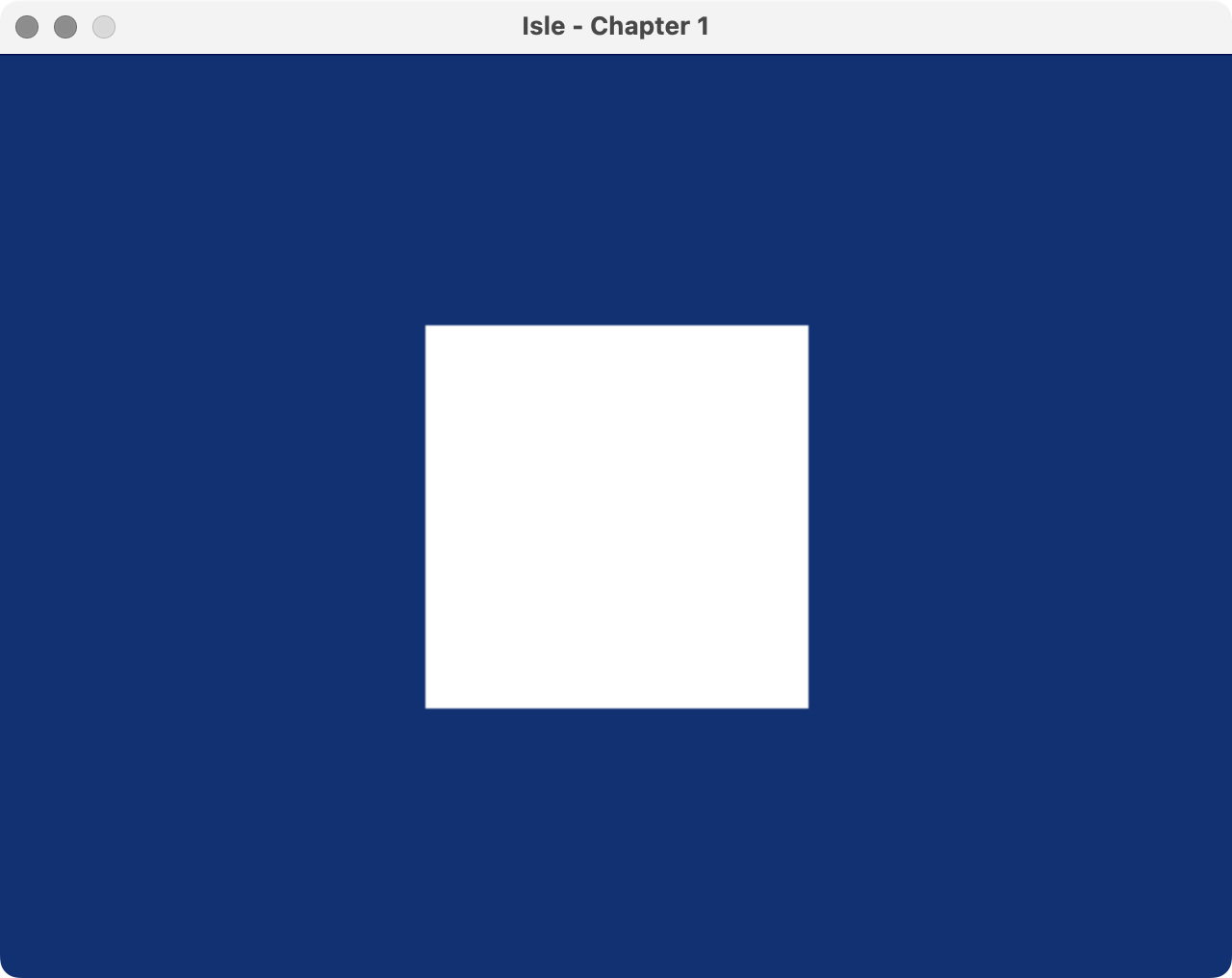
Without any memory to store bitmap graphics (yet), we're racing the beam, generating the colour of each pixel when the display needs it. Perhaps the simplest thing we can do is define a square using the coordinates from the display controller:
// define a square with display coordinates
//   HRES and VRES are defined in display_modes.vh
wire square = (dx >= HRES/2-100 && dx < HRES/2+100) &&
              (dy >= VRES/2-100 && dy < VRES/2+100);

// paint colour: white inside square, blue outside
wire [BPC-1:0] paint_r = (square) ? 'h1F : 'h02;
wire [BPC-1:0] paint_g = (square) ? 'h1F : 'h06;
wire [BPC-1:0] paint_b = (square) ? 'h1F : 'h0E;
We define a 200x200 pixel square in the centre of the display using the resolution parameters (HRES, VRES) from display_modes.vh.
To understand the paint colours, you need to know that Isle uses 15-bit colour (RGB555). Each colour has 5 bits, with a range of 0-31 (0x0-0x1F). See the post on Isle display modes for more details on 15-bit colour.
The following capture shows our square design running in Verilator/SDL simulation.
Video Signal Output
To get our graphics onto the display, we need to encode them into a suitable format and output them from the FPGA. Isle generates DVI signals that are upwardly compatible with HDMI. DVI and HDMI use transition-minimized differential signaling (TMDS) to encode each 8-bit colour channel as a robust 10-bit value for transmission as a high-frequency serial signal.
I am writing a separate post on DVI and TMDS, but for now, I'll summarise the DVI modules:
- Common
- hardware/gfx/tmds_encoder - TMDS Encoder (DVI)
- ECP5
- hardware/arch/ecp5/dvi_generator - DVI output with tmds_encoder and ODDRX1F
- XC7
- hardware/arch/xc7/dvi_generator - DVI output with tmds_encoder and oserdes_10b
- hardware/arch/xc7/oserdes_10b - 10:1 Output Serializer with OSERDESE2
- hardware/arch/xc7/tmds_out - TMDS Signal Output with OBUFDS
The Verilator/SDL simulation doesn't use DVI; it writes the display signal to a texture for rendering. The simulation uses a special 672x384 display mode to maximise simulation performance.
Top Level
Bringing our designs together, we have our first root Isle module hardware/book/ch01/ch01.v:
module ch01 #(
    parameter BPC=5,          // bits per colour channel
    parameter CORDW=16,       // signed coordinate width (bits)
    parameter DISPLAY_MODE=0  // display mode (see display_modes.vh)
    ) (
    input  wire clk,                        // system clock
    input  wire rst,                        // reset
    output reg  signed [CORDW-1:0] disp_x,  // horizontal display position
    output reg  signed [CORDW-1:0] disp_y,  // vertical display position
    output reg  disp_hsync,                 // horizontal display sync
    output reg  disp_vsync,                 // vertical display sync
    output reg  disp_de,                    // display data enable
    output reg  disp_frame,                 // high for one cycle at frame start
    output reg  [BPC-1:0] disp_r,           // red display channel
    output reg  [BPC-1:0] disp_g,           // green display channel
    output reg  [BPC-1:0] disp_b            // blue display channel
    );

    `include "display_modes.vh"

    //
    // Display Sync Signals and Coordinates
    //

    wire signed [CORDW-1:0] dx, dy;
    wire hsync, vsync, de;
    wire frame_start;

    display_sync_gen #(
        .CORDW(CORDW),
        .DISPLAY_MODE(DISPLAY_MODE)
    ) display_sync_gen_inst (
        .clk_pix(clk),
        .rst_pix(rst),
        .dx(dx),
        .dy(dy),
        .hsync(hsync),
        .vsync(vsync),
        .de(de),
        .frame_start(frame_start),
        .line_start()
    );

    //
    // Painting
    //

    // define a square with display coordinates
    //   HRES and VRES are defined in display_modes.vh
    wire square = (dx >= HRES/2-100 && dx < HRES/2+100) &&
                  (dy >= VRES/2-100 && dy < VRES/2+100);

    // paint colour: white inside square, blue outside
    wire [BPC-1:0] paint_r = (square) ? 'h1F : 'h02;
    wire [BPC-1:0] paint_g = (square) ? 'h1F : 'h06;
    wire [BPC-1:0] paint_b = (square) ? 'h1F : 'h0E;


    //
    // Display Output
    //

    // register display signals
    always @(posedge clk) begin
        disp_x <= dx;
        disp_y <= dy;
        disp_hsync <= hsync;
        disp_vsync <= vsync;
        disp_de <= de;
        disp_frame <= frame_start;
        disp_r <= (de) ? paint_r : 'h00;  // paint colour but black in blanking
        disp_g <= (de) ? paint_g : 'h00;
        disp_b <= (de) ? paint_b : 'h00;
    end
endmodule
This module creates an instance of the display sync generator, draws a square, and outputs the display signals.
But this isn't the top module and doesn't do the DVI signal generation. Instead, each board has its own top module with architecture and board-specific configuration. Keeping architecture-specific designs to the top module reduces code duplication and makes supporting multiple dev boards manageable. You'll find clock, DVI generation and board display signal handling in these short top modules:
- Lakritz: boards/lakritz/ch01/top_ch01.v
- Nexys Video: boards/nexys_video/ch01/top_ch01.v
- ULX3S: boards/ulx3s/ch01/top_ch01.v
- Verilator: boards/verilator/ch01/top_ch01.v
The Verilator simulation is easy to run on Linux/Mac/Windows, no dev board required.
Build & Program
Let's build this first, very simple iteration on Isle.
I've included a Makefile, constraints, and build instructions for each dev board:
You can open an issue if you have problems building Isle or spot a mistake on the blog. However, bear in mind I'm a team of one working in my spare time. Your board's forum or Discord channel is usually the best place to get help. Yosys has a Discourse group.
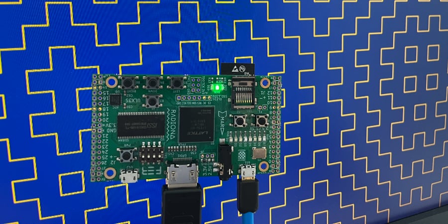
Once you have the square design running on your board, try the hitomezashi (一目刺し) stitch pattern or animated starfield from Isle Projects, by replacing the ch01 instance in your board's top module. You can also check out more ideas for racing the beam from my previous FPGA graphics blog series.
In the next chapter on bitmap graphics, we'll be adding vram and a framebuffer.
Next step: Chapter 2 - Bitmap Graphics, Display Modes, or Isle Index
Further Reading
- The Secret Life of the Television by Tim Hunkin (YouTube)