Isle Bitmap Graphics
Published 31 Aug 2025, Updated 06 June 2026 (DRAFT)
Generating pixels on the fly as we did in the previous display controller chapter, is fun, but it limits creativity and the types of programs we can run. In chapter 2 of Building Isle, we introduce bitmap graphics, where pixels on screen are held in memory instead of being generated at the moment we need them. We paint pixels into video memory, then read each pixel for display as needed.
If you're new to the project, read Isle FPGA Computer for an introduction. See Isle Index for more pages.
Memory/Resolution/Colour
I was determined that Isle would run on small FPGAs, so it was accessible and affordable to as many people as possible. However, I also wanted dedicated vram using FPGA block ram (bram), instead of graphics sharing memory with the CPU. Using dedicated bram for video memory avoids contention with the CPU, but also let's us do some pretty cool things with colour depth and clock domains.
With bram, we can have two memory ports, so it's no problem if the graphics engine is drawing shapes at the same time as the display reads pixels. Each bram port can run at a different frequency, so we can support different display modes (1366x768, 1024x768, 1280x720) without changing our system clock or handling tricky clock domain crossing issues.
FPGA bram is ideal for our video memory, but it's also in short supply, especially on smaller FPGAs, so I've chosen to design Isle with 64 KiB of vram. That sounds tiny, but there's a surprising amount we can do with 64 KiB, especially as block ram is so flexible.
Bitmap Resolution
Example Isle bitmap resolutions with 64 KiB vram:
- lores: 336x192 and 256x192
- Dual 16-colour (4-bit) buffers
- Single 256-colour (8-bit) buffer
- hires: 672x384 and 512x384
- Dual 2-colour (1-bit) buffers
- Single 4-colour (2-bit) buffer
These resolutions are enough for many types of program, including GUIs and games. Resolution and colour depth are flexible, so don't feel constrained by my choices, though bear in mind how much video memory you'll need. I explain the resolution and colour choices in more detail in display modes.
Video RAM
Isle video ram (vram) has a 32-bit data bus, matching our CPU data bus for good performance and simple addressing. Depending on the colour mode, each pixel is represented by 1, 2, 4, or 8 bits. If we use regular memory for vram, updating a pixel is fiddly and time-consuming, we need to read a 32-bit word, mask out the bits we want to change, then write the word back. Taking advantage of the flexibility of block ram (bram), we can have 32-bit write mask to control exactly which bits get updated when writing to memory. For example, with a 4 colour (2-bit) bitmap, we can write a single 2-bit pixel in a single operation.
The Verilog vram design is surprisingly simple hardware/mem/vram.v (doc):
module vram #(
    parameter ADDRW=14,      // address width ≥14 (bits)
    parameter FILE_BMAP="",  // optional initial bitmap to load
    parameter WORD=32        // machine word size (bits)
    ) (
    input  wire clk_sys,                // system clock
    input  wire clk_pix,                // pixel clock
    input  wire [WORD-1:0] wmask_sys,   // system write mask
    input  wire re_sys,                 // system read enable
    input  wire [ADDRW-1:0] addr_sys,   // system word address
    input  wire [WORD-1:0] din_sys,     // system data in
    output reg  [WORD-1:0] dout_sys,    // system data out
    input  wire [ADDRW-1:0] addr_disp,  // display word address
    output reg  [WORD-1:0] dout_disp    // display data out
    );

    localparam DEPTH=2**ADDRW;

    reg [WORD-1:0] vram_mem [0:DEPTH-1];

    initial begin
        if (FILE_BMAP != "") begin
            $display("Load bitmap file '%s' into vram.", FILE_BMAP);
            $readmemh(FILE_BMAP, vram_mem);
        end
    end

    // system port (read-write)
    integer i;
    always @(posedge clk_sys) begin
        if (re_sys) dout_sys <= vram_mem[addr_sys];
        for (i=0; i<WORD; i=i+1) begin
            if (wmask_sys[i]) vram_mem[addr_sys][i] <= din_sys[i];
        end
    end

    // display port (read-only with additional output register)
    reg [WORD-1:0] dout_disp_reg;
    always @(posedge clk_pix) begin
        dout_disp_reg <= vram_mem[addr_disp];
        dout_disp <= dout_disp_reg;
    end
endmoduleColour Lookup Table
A small vram limits the number of different colours we can have, but it's less of a restriction than it first appears. Instead of storing the colour of each pixel in vram, we store an index. When we display a pixel, we look up that index in a table to find the RGB colour to display. The table is a colour lookup table or clut. This technique is referred to as indexed colour and is also used by PNG and GIF graphics formats.
With 4 bits per pixel, we have 16 different colours, but we can choose them from the 32,768 15-bit colours.

For example, the display hardware loads a pixel's data from vram, and the colour index is 0x3. We send the number 0x3 to the clut and it gives us the light blue colour 0x0A76 (using the Go-16 palette). We then split this into its component colours for output to the display: RGB(02, 19, 22).
Each colour channel (red/green/blue) is 5 bits (0-31), so it's hard to judge by eye what the colour is from its hex value. Isle includes a simple Python tool, rgbconv, that converts colours to/from 15-bit RGB.
The clut module has a similar dual-port design to vram: hardware/mem/clut.v (doc). The CPU can read and write palette entries on one port, while the display is free to use the other port. You can see an example of the CPU loading a palette in chapter 5 software.
Canvas & Buffer
We could setup a fixed relationship between memory and screen, memory address 0 is pixel (0, 0), address 1 is pixel (1, 0) etc. However, this is inflexible and creates problems when our bitmap dimensions don't match the screen. A canvas is a simple abstraction that gives us more control over bitmap display.
A canvas renders a bitmap image at a particular location on the screen, known as the canvas window. For example, we can display a 256x256 bitmap starting at coordinates (32, 48) and ending at (287, 303), so it's offset from the edge of the screen.
Isle canvases support scaling in hardware, so bitmap graphics can fill the screen even when it's lower resolution than the screen's native resolution. For example, if we scale a 512x384 canvas by a factor of two, it fills a 1024x768 screen.
The actual pixel data is held in a canvas buffer in vram, and a canvas can have multiple buffers, commonly used for double buffering. With double buffering, we're free to paint whatever we like in one buffer, while the display shows the other. When painting is complete, we swap buffers. We'll see examples of double buffering in later chapters. Also in later chapters, we'll see how you combine multiple canvases of different resolutions, or overlay one canvas on top of another for animation and parallax effects.
|-------------------------------|
|  win_start            display |
|        *----------|           |
|        |  canvas  |           |
|        |          |           |
|        |----------*           |
|                    win_end    |
|                               |
|-------------------------------|
How canvas position is controlled by window signals (draft diagram).
Bitmap Display Chain
There are three steps to displaying a bitmap graphic (module):
- Calculate the pixel's vram address (canv_disp_agu)
- Read the pixel data from vram (vram)
- Read the RGB display colour from the palette (clut)
You can see these steps in the chapter 2 root design hardware/book/ch02/ch02.v (discussed in more detail shortly). We've already discussed the vram and clut, but address generation is the vital first step.
Each of the three bitmap display steps takes 2 cycles in the Isle design, so the latency is 6 cycles.
Canvas Display Address
The display needs to know which pixel to show for each display coordinate (dx, dy). We need to account for the canvas window position, scaling, the bit depth, and the latency of the different stages in the bitmap display chain. The canvas display Address Generation Unit (AGU) handles this.
Isle vram had a 32 bit data bus, but each canvas pixel might be 1, 2, 4, or 8 bits. The AGU calculates the vram address and where in the 32-bit word to find a particular pixel, this is the pixel ID. For example, with a 4 bit (16 colour) canvas, there are eight pixels in each 32-bit word.
I'm not going to dig into the AGU details in this post. You see the Verilog source and reference in the Isle repo: hardware/gfx/canv_disp_agu.v (doc).
Testing
I wanted to test the bitmap display logic end-to-end. It's easy to make mistakes with latency in the display chain, leading to pixels appearing in the wrong place or even the wrong colour. I created a test graphic, which has different coloured pixels in the corners of the image. We can use this test graphic two ways: with an automated test bench and to visually check the display on dev boards.
You can find the end-to-end test in hardware/tests/book and test instructions in hardware/tests/README.md.
Here's a sample test run, showing some example results (trimmed for brevity):
$ make ch02
...
Load bitmap file '../../../res/bitmap/latency/latency-672x384.mem' into vram.
Load palette file '../../../res/bitmap/latency/latency-672x384_palette.mem"' into clut.
4389244.00ns INFO     cocotb.ch02                        RGB(14, 8,17) at (   0,   0)
4389284.00ns INFO     cocotb.ch02                        RGB(12,19,31) at (   1,   0)
4389324.00ns INFO     cocotb.ch02                        RGB(31,30, 6) at (   2,   0)
...
16672004.00ns INFO     cocotb.ch02                        RGB(31,30, 6) at ( 669, 383)
16672044.00ns INFO     cocotb.ch02                        RGB(14, 8,17) at ( 670, 383)
16672084.00ns INFO     cocotb.ch02                        RGB(12,19,31) at ( 671, 383)
16704084.00ns INFO     cocotb.regression                  pixel_colour passed
Image is Everything
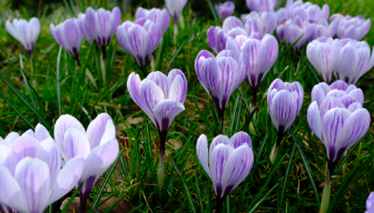
Even without a CPU or a graphics engine we can load an image into vram at build time using the Verilog $readmemh function. A sample image lets us visually confirm bitmap graphics output is working and supports automated testing. We load the image's colour palette into the clut, which performs the colour palette lookups as we discused earlier.
I've used a photograph of purple crocuses from my local park.

Creating Your Own Images
You can convert your own images into $readmemh format using img2fmem. You can find img2fmem in the Project F FPGA Tools repo. Ensure your image has the correct dimensions before conversion.
For example, to convert crocus.png into a 4-bit image with a 15-bit palette packed into 32-bits:
img2fmem.py crocus.png 4 mem 15 32For details on img2fmem installation and command-line options, see the img2fmem README.
Complete Design
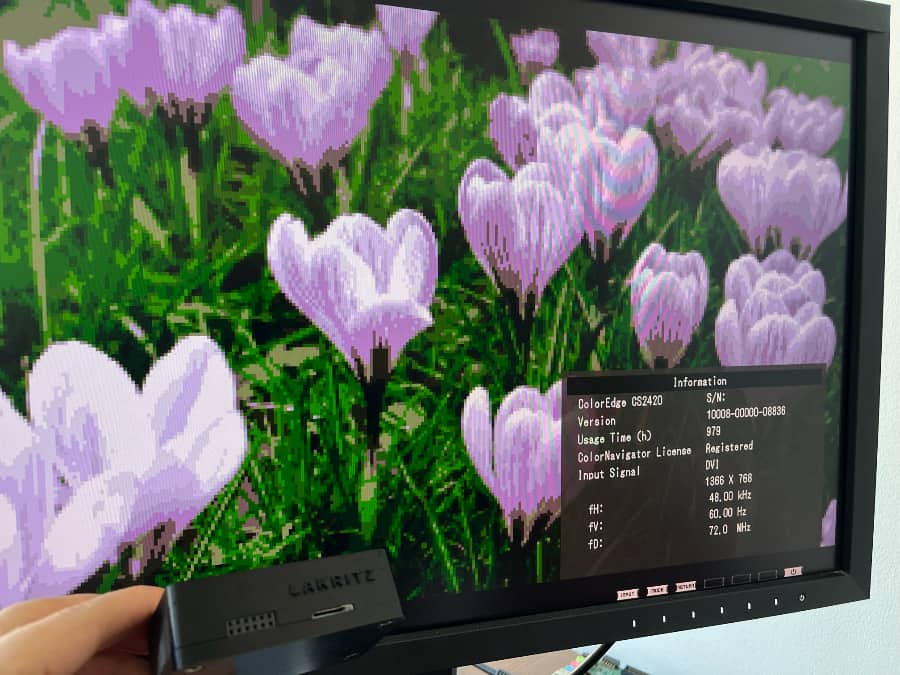
For this chapter, I've created a simple design that shows the 16 colour crocus image with a 1366x768 display. However, all the hardware is in place to support 2, 4, 16, and 256 colour images at different resolutions. Use your own images and experiment with parameters in the top module for your board.
Each dev board has its own top module:
- Lakritz: boards/lakritz/ch02/top_ch02.v (build instructions)
- Nexys Video: boards/nexys_video/ch02/top_ch02.v (build instructions)
- ULX3S: boards/ulx3s/ch02/top_ch02.v (build instructions)
- Verilator: boards/verilator/ch02/top_ch02.v (build instructions)
But it's in the chapter 2 root module that the interesting logic happens:
module ch02 #(
    parameter BPC=5,           // bits per colour channel
    parameter BG_COLR='h0886,  // background colour (RGB555)
    parameter CANV_BPP=4,      // canvas bits per pixel (4=16 colours)
    parameter CANV_LORES=0,    // low resolution canvas flag (double scaling)
    parameter CORDW=16,        // signed coordinate width (bits)
    parameter DISPLAY_MODE=0,  // display mode (see display_modes.vh)
    parameter FILE_BMAP="",    // initial bitmap file for framebuffer
    parameter FILE_PAL=""      // initial palette for CLUT
    ) (
    input  wire clk,                        // system clock
    input  wire rst,                        // reset
    output reg  signed [CORDW-1:0] disp_x,  // horizontal display position
    output reg  signed [CORDW-1:0] disp_y,  // vertical display position
    output reg  disp_hsync,                 // horizontal display sync
    output reg  disp_vsync,                 // vertical display sync
    output reg  disp_de,                    // display data enable
    output reg  disp_frame,                 // high for one cycle at frame start
    output reg  [BPC-1:0] disp_r,           // red display channel
    output reg  [BPC-1:0] disp_g,           // green display channel
    output reg  [BPC-1:0] disp_b            // blue display channel
    );

    `include "display_modes.vh"

    // vram - 16K x 32-bit (64 KiB) with bit write
    //   NB. Due to bit write, minimum depth is 64 KiB with 18 Kb bram
    localparam VRAM_ADDRW = 14;  // vram address width (bits)
    localparam VRAM_LAT   =  2;  // vram display read latency (cycles; min=1)

    // internal system params
    localparam WORD = 32;  // machine word size (bits)
    localparam CIDX_ADDRW = 8;   // colour index address width 2^8 = 256 colours
    localparam COLRW = 3 * BPC;  // colour width across three channels (bits)
    localparam CANV_SHIFTW = 3;  // max shift is 5 bits (2^5 = 32 bits)
    localparam PIX_IDW=$clog2(WORD);  // pixel ID width (bits)
    localparam CLUT_LAT =   2;   // clut display read latency (cycles; min=1)

    // display signals
    wire signed [CORDW-1:0] dx, dy;
    wire hsync, vsync, de;
    wire frame_start, line_start;


    //
    // Video RAM (vram)
    //

    wire [VRAM_ADDRW-1:0] vram_addr_disp;
    wire [WORD-1:0] vram_dout_disp;

    // signals for future Earthrise/CPU use
    wire [WORD-1:0] vram_wmask_sys = 0;
    wire vram_re_sys = 0;
    wire [VRAM_ADDRW-1:0] vram_addr_sys = 0;
    wire [WORD-1:0] vram_din_sys = 0;
    wire [WORD-1:0] vram_dout_sys;

    vram #(
        .WORD(WORD),
        .ADDRW(VRAM_ADDRW),
        .FILE_BMAP(FILE_BMAP)
        ) vram_inst (
        .clk_sys(clk),
        .clk_pix(clk),
        .wmask_sys(vram_wmask_sys),
        .re_sys(vram_re_sys),
        .addr_sys(vram_addr_sys),
        .din_sys(vram_din_sys),
        .dout_sys(vram_dout_sys),
        .addr_disp(vram_addr_disp),
        .dout_disp(vram_dout_disp)
    );


    //
    // Canvas Display Address
    //

    wire [CANV_SHIFTW-1:0] canv_addr_shift;  // address shift based on canvas bits per pixel
    wire [VRAM_ADDRW-1:0] canv_addr;  // pixel memory address
    wire [$clog2(WORD)-1:0] canv_pix_id;  // pixel ID within word
    wire canv_paint;

    // CANV_BPP is currently a parameter, but will be hardware register later
    assign canv_addr_shift = 5 - $clog2(CANV_BPP);

    canv_disp_agu #(
        .ADDRW(VRAM_ADDRW),
        .CLUT_LAT(CLUT_LAT),
        .CORDW(CORDW),
        .SHIFTW(CANV_SHIFTW),
        .VRAM_LAT(VRAM_LAT),
        .WORD(WORD)
    ) canv_disp_agu_inst (
        .clk_pix(clk),
        .rst_pix(rst),
        .frame_start(frame_start),
        .line_start(line_start),
        .dx(dx),
        .dy(dy),
        .addr_base({VRAM_ADDRW{1'b0}}),  // fixed base address for now
        .addr_shift(canv_addr_shift),
        .win_start(WIN_START_CORD),
        .win_end(WIN_END_CORD),
        .scale(CANV_LORES ? DISPLAY_SCALE << 1 : DISPLAY_SCALE),
        .addr(canv_addr),
        .pix_id(canv_pix_id),
        .paint(canv_paint)
    );


    //
    // CLUT
    //

    reg  [CIDX_ADDRW-1:0] clut_addr_disp;
    wire [COLRW-1:0] clut_dout_disp;

    // signals for future CPU use
    wire clut_we_sys = 0;
    wire clut_re_sys = 0;
    wire [CIDX_ADDRW-1:0] clut_addr_sys = 0;
    wire [COLRW-1:0] clut_din_sys = 0;
    wire [COLRW-1:0] clut_dout_sys;

    clut #(
        .ADDRW(CIDX_ADDRW),
        .DATAW(COLRW),
        .FILE_PAL(FILE_PAL)
    ) clut_inst (
        .clk_sys(clk),
        .clk_pix(clk),
        .we_sys(clut_we_sys),
        .re_sys(clut_re_sys),
        .addr_sys(clut_addr_sys),
        .din_sys(clut_din_sys),
        .dout_sys(clut_dout_sys),
        .addr_disp(clut_addr_disp),
        .dout_disp(clut_dout_disp)
    );


    //
    // Display Sync Signals and Coordinates
    //

    display_sync_gen #(
        .CORDW(CORDW),
        .DISPLAY_MODE(DISPLAY_MODE)
    ) display_sync_gen_inst (
        .clk_pix(clk),
        .rst_pix(rst),
        .dx(dx),
        .dy(dy),
        .hsync(hsync),
        .vsync(vsync),
        .de(de),
        .frame_start(frame_start),
        .line_start(line_start)
    );


    //
    // Painting & Display Output
    //

    assign vram_addr_disp = canv_addr;

    // delay pix_id for vram latency
    reg [PIX_IDW-1:0] pix_id_pipe [0:VRAM_LAT-1];
    integer i;
    always @(posedge clk) begin
        pix_id_pipe[0] <= canv_pix_id;
        for (i=1; i<VRAM_LAT; i=i+1)
            pix_id_pipe[i] <= pix_id_pipe[i-1];
    end
    wire [PIX_IDW-1:0] pix_id_disp = pix_id_pipe[VRAM_LAT-1];

    // select pixel ID from word depending on colour depth
    reg [CIDX_ADDRW-1:0] pcidx_1, pcidx_2, pcidx_4, pcidx_8;
    always @(*) begin
        pcidx_1 = (vram_dout_disp >> pix_id_disp)        & 'b1;
        pcidx_2 = (vram_dout_disp >> (pix_id_disp << 1)) & 'b11;
        pcidx_4 = (vram_dout_disp >> (pix_id_disp << 2)) & 'b1111;
        pcidx_8 = (vram_dout_disp >> (pix_id_disp << 3)) & 'b11111111;
        case (CANV_BPP)
            1: clut_addr_disp = pcidx_1;
            2: clut_addr_disp = pcidx_2;
            4: clut_addr_disp = pcidx_4;
            8: clut_addr_disp = pcidx_8;
            default: clut_addr_disp = pcidx_4;
        endcase
    end

    // delay background visibility for clut latency
    wire [CLUT_LAT-1:0] bg_visible = {{(CLUT_LAT-1){1'b0}}, ~canv_paint};
    reg  [CLUT_LAT-1:0] bg_visible_pipe;
    always @(posedge clk) bg_visible_pipe <= (bg_visible_pipe << 1) | bg_visible;

    // paint colours
    reg [BPC-1:0] paint_r, paint_g, paint_b;
    always @(*) {paint_r, paint_g, paint_b} = bg_visible_pipe[CLUT_LAT-1] ? BG_COLR : clut_dout_disp;

    // register display signals
    always @(posedge clk) begin
        disp_x <= dx;
        disp_y <= dy;
        disp_hsync <= hsync;
        disp_vsync <= vsync;
        disp_de <= de;
        disp_frame <= frame_start;
        disp_r <= (de) ? paint_r : 'h0;  // paint colour but black in blanking
        disp_g <= (de) ? paint_g : 'h0;
        disp_b <= (de) ? paint_b : 'h0;
    end
endmodule
The system port on the vram and clut aren't used in this design, but will support the Earthrise graphics engine and RISC-V CPU.
Extracting a Pixel
In the Painting & Display Output section of ch02.v we extract the pixel colour index from the vram data before passing it to the colour lookup table.
A canvas could be 1, 2, 4, or 8 bit. In this chapter, it's hard-coded at design time, but when we introduce a CPU you'll be able to change it at runtime. To handle different bit depths, we extract the pixel for all potential bit depths then select the one we want.
For example, let's say we want the 7th pixel from the 32-bit data returned from vram. For a 1-bit canvas, we right shift the vram data by 7 bits (7 × 1) then AND it with 1 to select a single bit. For a 4-bit canvas, we right shift the vram data by the 28 bits (7 × 4), then AND it with 15 (1111 in binary) to select four bits.
Ready to Draw
This chapter is pretty dry, but with our bitmap graphics in place, we're ready to introduce our 2D graphics engine, Earthrise. Earthrise is a simple processor that decodes and executes graphics instructions for pixels, lines, triangles, rects, and circles.
Next step: Chapter 3 - 2D Drawing, Display Modes, or Isle Index