FPGA Sine Lookup Table
In this how to, we’re going to look at a straightforward method for generating sine and cosine using a lookup table. There are more precise methods, but this one is fast and simple and will suffice for many applications. New to Verilog maths? Check out my introduction to Numbers in Verilog.
Share your thoughts with @WillFlux on Mastodon or Twitter. If you like what I do, sponsor me. 🙏
Source
The SystemVerilog designs featured in this post are available from the Project F Library under the open-source MIT licence: build on them to your heart’s content. The rest of the blog content is subject to standard copyright restrictions: don’t republish it without permission.
Look Up, Don’t Calculate!
A lookup table can produce a result directly without complex calculation for both sine and cosine.
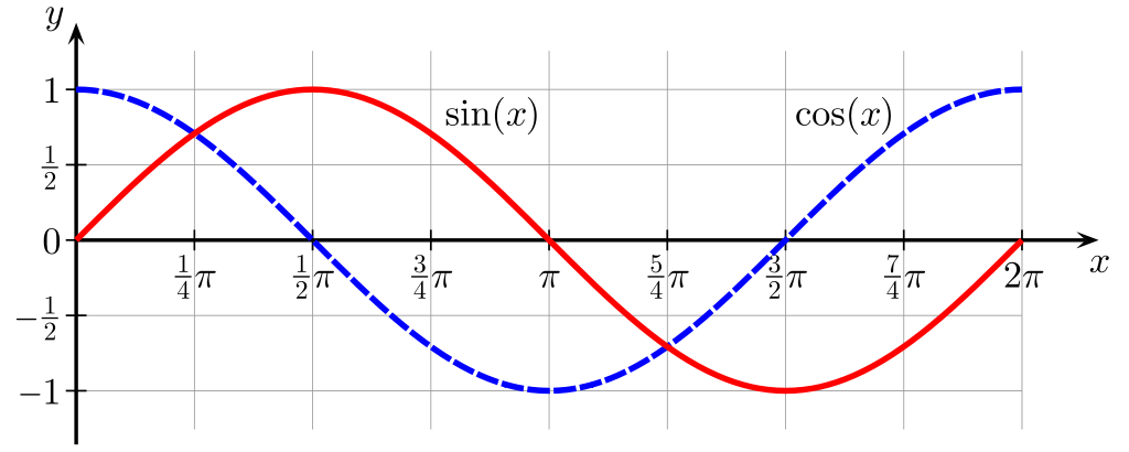
Graph image by Geek3 in the public domain.
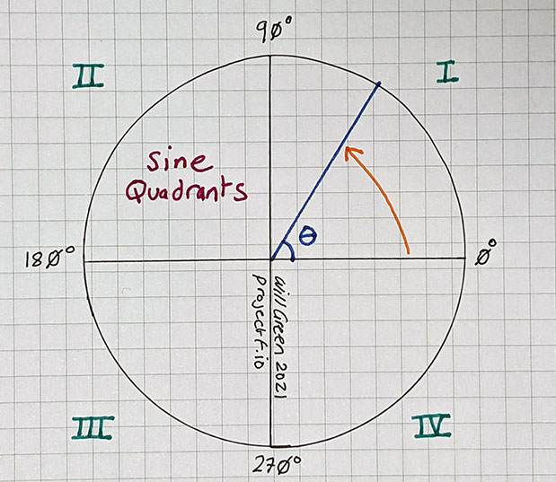
Sine Quadrants
Sine has a simple symmetry to it (see diagram above), so our table only needs to cover a quarter of a circle: 0 to 90 degrees. Our Verilog will handle a complete circle using simple adjustment for each of the four quadrants.
The following diagram shows the quadrants and how angles are measured anti-clockwise from the three o’clock position on the circle.
Wikipedia has a summary of properties relating to the quadrants.
Generate Table
The Project F maths library includes a 64 entry sine table you can use: [sine_table_64x8.mem].
If you’re happy to use this table, you can skip ahead to Sine Table Module.
Alternatively, I’ve created a short Python script that can generate tables to your specification [sine2fmem]:
#!/usr/bin/env python3

from math import ceil, sin, pi
import sys

# math.sin works in radians: 0-90° == π/2 radians

if (len(sys.argv) > 1):
    rows = int(sys.argv[1])
else:
    rows = 256

if (len(sys.argv) > 2):
    width = int(sys.argv[2])
else:
    width = 16

print("// Generated by sine2fmem.py from Project F")
print("// Learn more at https://github.com/projf/fpgatools")

fmt_width = str(ceil(width/4))  # four bits per hex digit
fmt_string = "{:0" + fmt_width + "X}  // {:03}: sin({:.4f}) = {:.4f}"

for i in range(rows):
    val = (pi/(2*rows)) * i
    res = sin(val)
    res_scaled = round((2**width) * res)
    if res_scaled == 2**width:  # maximum value uses too many bits
        res_scaled -= 1;        # accompanying Verilog module handles this
    print(fmt_string.format(res_scaled, i, val, res))
You specify the number rows in your table and their width in bits. I strongly recommend using a power of two for the rows, so the values wrap naturally.
The sine2fmem README has more details on the workings of the script, including examples.
Sine Table Module
I’ve created a simple Verilog module that looks up the correct value, adjusting for the quadrant of the circle it falls in [sine_table.sv]:
module sine_table #(
    parameter ROM_DEPTH=64,  // number of entries in sine ROM for 0° to 90°
    parameter ROM_WIDTH=8,   // width of sine ROM data in bits
    parameter ROM_FILE="",   // sine table file to populate ROM
    parameter ADDRW=$clog2(4*ROM_DEPTH)  // full circle is 0° to 360°
    ) (
    input  wire logic [ADDRW-1:0] id,  // table ID to lookup
    output      logic signed [2*ROM_WIDTH-1:0] data  // answer (fixed-point)
    );

    // sine table ROM: 0°-90°
    logic [$clog2(ROM_DEPTH)-1:0] tab_id;
    logic [ROM_WIDTH-1:0] tab_data;
    rom_async #(
        .WIDTH(ROM_WIDTH),
        .DEPTH(ROM_DEPTH),
        .INIT_F(ROM_FILE)
    ) sine_rom (
        .addr(tab_id),
        .data(tab_data)
    );

    logic [1:0] quad;  // quadrant we're in: I, II, III, IV
    always_comb begin
        quad = id[ADDRW-1:ADDRW-2];
        case (quad)
            2'b00: tab_id = id[ADDRW-3:0];                //  I:    0° to  90°
            2'b01: tab_id = 2*ROM_DEPTH - id[ADDRW-3:0];  // II:   90° to 180°
            2'b10: tab_id = id[ADDRW-3:0] - 2*ROM_DEPTH;  // III: 180° to 270°
            2'b11: tab_id = 4*ROM_DEPTH - id[ADDRW-3:0];  // IV:  270° to 360°
        endcase
    end

    always_comb begin
        if (id == ROM_DEPTH) begin  // sin(90°) = +1.0
            data = {{ROM_WIDTH-1{1'b0}}, 1'b1, {ROM_WIDTH{1'b0}}};
        end else if (id == 3*ROM_DEPTH) begin  // sin(270°) = -1.0
            data = {{ROM_WIDTH{1'b1}}, {ROM_WIDTH{1'b0}}};
        end else begin
            if (quad[1] == 0) begin  // positive in quadrant I and II
                data = {{ROM_WIDTH{1'b0}}, tab_data};
            end else begin
                data = {2*ROM_WIDTH{1'b0}} - {{ROM_WIDTH{1'b0}}, tab_data};
            end
        end
    end
endmodule
NB. This module outputs combinational logic, so you may want to register the results depending on your design and FPGA. I may change this in future versions if it proves to be too much of a timing headache.
Test Bench
There is a Vivado test bench available in the library: [sine_table_tb.sv]. A Verilator test example will be added later.
Module Usage
The output is signed fixed-point, with twice the width of the ROM data. For example, if you have an 8-bit table, you’ll get a 16-bit signed result with eight integer and eight fractional bits (Q8.8). If you’re new to fixed point, check out Fixed Point Numbers in Verilog.
    localparam ROM_DEPTH=64;    // number of entries in sine ROM for 0° to 90°
    localparam ROM_WIDTH=8;     // width of sine ROM data
    localparam ROM_FILE="sine_table_64x8.mem";  // file to populate ROM
    localparam ADDRW=$clog2(4*ROM_DEPTH);  // full circle is 0° to 360°

    logic [ADDRW-1:0] id;  // table ID to lookup
    logic signed [2*ROM_WIDTH-1:0] data; // answer
    sine_table #(
        .ROM_DEPTH(ROM_DEPTH),
        .ROM_WIDTH(ROM_WIDTH),
        .ROM_FILE(ROM_FILE)
    ) sine_table_inst (
        .id,
        .data
    );
Practical usage is straightforward; let’s look at some examples.
Sine 30°
First, you find the id that equates to 30 degrees.
Our ROM has 64 entries covering 90°, so we want 30 x 64/90 = 21.333, which rounds to 21.
For id=21 the module returns: 00000000.01111110 == 0.492188
As you may know, sin(30) = 0.5 exactly. Out value isn’t quite right, but we can’t represent 30 degrees exactly using a power of two. You can increase your accuracy by using a larger table at the cost of more logic. However, for exact values, you’re probably better of calculating them in logic, a topic we plan to cover at a later date.
Sine -45°
How about -45°, which is equivalent to 315° (360-45)?
315 x 64/90 = 224, an exact value!
For id=224 the module returns: 11111111.01001011 == -0.707031
My HP 35s calculator gives a value of -0.707107. In this case, our accuracy is limited by using only 8-bits for the fractional part of the answer: the smallest value we can represent is 1/256 = ~0.004, so we can’t expect more than two decimal places of accuracy.
Cosine 30°
Cosine is offset from sine by 90°. Calculating cosine is as simple as subtracting the angle from 90° before determining the id.
For example, to calculate the cosine of 30°:
Subtract the angle from 90: 90-30 = 60, then convert to id: 60 x 64/90 = 42.666, which rounds to 43.
For id=43 the module returns: 00000000.11011111 == 0.871094
My HP 35s calculator gives a value of 0.8660254.
Practical Examples
You can see this module in action in my Sine Scroller demo.

ROM Implementation
The sine table module loads the sine table data into an asynchronous ROM [rom_async.sv]:
module rom_async #(
    parameter WIDTH=8,
    parameter DEPTH=256,
    parameter INIT_F="",
    localparam ADDRW=$clog2(DEPTH)
    ) (
    input wire logic [ADDRW-1:0] addr,
    output     logic [WIDTH-1:0] data
    );

    logic [WIDTH-1:0] memory [DEPTH];

    initial begin
        if (INIT_F != 0) begin
            $display("Creating rom_async from init file '%s'.", INIT_F);
            $readmemh(INIT_F, memory);
        end
    end

    always_comb data = memory[addr];
endmodule
Small tables work well with rom_async. For more substantial lookup tables, block ram (BRAM) is a better choice. To use BRAM, substitute rom_sync into the design and add a clock signal. Beware of the additional cycle of latency when using BRAM.
What’s Next?
That wraps up this FPGA recipe, but you might like to check out Division in Verilog or Square Root.